
Drivetrain BSH catch can and dual boost port install
#451
 06-28-2011, 09:22 AM


Get with DoS, DetroitTuned, WayMotorWorks and CustomMINIShop. The N18 Competition Catch Can Kit is coming VERRRRY Soon (Within 2 weeks) and these guys will have it 
WOW! Glad you kept that out of your intercooler/intake manifold so you not right back at the dealership asking for another walnut shelling! 
Dave, thanks for posting this up... how many miles is being shown here? And do you have a Boost Tap (as a block off) on as well?

Catch Can with Boost Port block installed 4/4/11 @ 25,500 miles after dealership carbon blasting with walnut media.
Currently 6/27/11 @ 29,000.
This is a small pint jar, not a normal quart mason.

BSH Catch Can Juice
Currently 6/27/11 @ 29,000.
This is a small pint jar, not a normal quart mason.
BSH Catch Can Juice
Dave, thanks for posting this up... how many miles is being shown here? And do you have a Boost Tap (as a block off) on as well?

#452
06-28-2011, 09:32 AM

#453
06-28-2011, 11:42 AM

#454
06-28-2011, 02:21 PM

4th Gear
Join Date: Apr 2011
Location: Irvine, CA
Posts: 462
Likes: 0
Received 0 Likes
on
0 Posts
thanks for the info. one question for a concerned N18 owner. do you guys have any idea what MINI did with the pcv valve where people have installed the boost tap on N14 engines to block off? are those gases/vapors being internally recirculated back to the intake manifold? thanks in advance for any info, and thanks for bringing an N18 application to the market.
#455
06-29-2011, 05:04 PM

Jomama,
Thank you for your question. It is now common practice for OEM’s to merge crank case pressures in the valve cover to be excavated through either a pair or a single outlet. As many early adopters of the twin exit design ran into frequent failure on the check valves that were intended to stop pressure created by the turbocharger to leading to costly warranty repairs it is now much more common place to see single outlet systems which are vacuum only. The N18 and N54 are good examples of this. This single exit design is also the fundamental principle behind our N14 catch can kit/boost tap combo.
Inside of the valve cover there will be a some sort of baffling, typically a series of half height walls, that will slow down blowby gasses and collect some of the oil held in them. There will be a series of drains inside of the valve cover that will drain this oil directly back into the oil pan. The concept of these drains going to the intake ports is not only incorrect, it is completely illogical so please let us put that to rest. Put simply, the level of complexity in the preventative measures to stop boost pressure and the possibility of backfire flash from entering the crank case is outrageous. As seen by end users, this baffle system alone does not suffice for either the performance driver or the automotive enthusiast whom puts pride in their vehicle.
Furthermore, the single outlet design is the superior means of crank case ventilation. The intake pre turbo provides a constant low pressure area for blowby gasses to escape to without the potential for boost pressure to ever act on the PCV system. This meets all requirements of a PCV system in both function and emissions compliance and with an able catch can in the loop it meets the needs of those who demand more as well.
All the best,
BSH
#456
06-29-2011, 05:08 PM
3rd Gear
Join Date: Sep 2008
Location: San Ramon, CA East Bay
Posts: 174
Likes: 0
Received 0 Likes
on
0 Posts
#457
06-29-2011, 05:12 PM
leomulhollandiii,
Although the Catch Can for the N18 will be the same basic design as the N14, the fittings involved with having a NO Hose Cutting solution will be very different and quite a bit more costly. More information as to what is in the kit as well as pricing will come from the dealers WayMotorWorks, DefendersOfSpeed, DetroitTuned and CustomMINIShop when the kit is made available to them.
Although the Catch Can for the N18 will be the same basic design as the N14, the fittings involved with having a NO Hose Cutting solution will be very different and quite a bit more costly. More information as to what is in the kit as well as pricing will come from the dealers WayMotorWorks, DefendersOfSpeed, DetroitTuned and CustomMINIShop when the kit is made available to them.
#458
06-29-2011, 05:15 PM
3rd Gear
Join Date: Sep 2008
Location: San Ramon, CA East Bay
Posts: 174
Likes: 0
Received 0 Likes
on
0 Posts
leomulhollandiii,
Although the Catch Can for the N18 will be the same basic design as the N14, the fittings involved with having a NO Hose Cutting solution will be very different and quite a bit more costly. More information as to what is in the kit as well as pricing will come from the dealers WayMotorWorks, DefendersOfSpeed, DetroitTuned and CustomMINIShop when the kit is made available to them.
Although the Catch Can for the N18 will be the same basic design as the N14, the fittings involved with having a NO Hose Cutting solution will be very different and quite a bit more costly. More information as to what is in the kit as well as pricing will come from the dealers WayMotorWorks, DefendersOfSpeed, DetroitTuned and CustomMINIShop when the kit is made available to them.
#459
06-29-2011, 05:15 PM
The can will physically look the same, however it uses our next gen baffle system which is new this year. We bought a new machine last year that allows us to do some pretty trick sheet work now.
 All of our kits now ship like this however.
 The rest of the kit will be N18 specific as Sush mentioned.
#460
06-29-2011, 05:31 PM
4th Gear
Join Date: Apr 2011
Location: Irvine, CA
Posts: 462
Likes: 0
Received 0 Likes
on
0 Posts
Jomama,
Thank you for your question. It is now common practice for OEM�s to merge crank case pressures in the valve cover to be excavated through either a pair or a single outlet. As many early adopters of the twin exit design ran into frequent failure on the check valves that were intended to stop pressure created by the turbocharger to leading to costly warranty repairs it is now much more common place to see single outlet systems which are vacuum only. The N18 and N54 are good examples of this. This single exit design is also the fundamental principle behind our N14 catch can kit/boost tap combo.
Inside of the valve cover there will be a some sort of baffling, typically a series of half height walls, that will slow down blowby gasses and collect some of the oil held in them. There will be a series of drains inside of the valve cover that will drain this oil directly back into the oil pan. The concept of these drains going to the intake ports is not only incorrect, it is completely illogical so please let us put that to rest. Put simply, the level of complexity in the preventative measures to stop boost pressure and the possibility of backfire flash from entering the crank case is outrageous. As seen by end users, this baffle system alone does not suffice for either the performance driver or the automotive enthusiast whom puts pride in their vehicle.
Furthermore, the single outlet design is the superior means of crank case ventilation. The intake pre turbo provides a constant low pressure area for blowby gasses to escape to without the potential for boost pressure to ever act on the PCV system. This meets all requirements of a PCV system in both function and emissions compliance and with an able catch can in the loop it meets the needs of those who demand more as well.
All the best,
BSH
thanks for the information! i'm glad to hear that the N18 functions the way you described it. so is it safe to assume that you guys will be providing a competition occ (with the dipstick) for the N18s? and it sounds like it will be a little more money than what the N14 occ sells for, if i read sush's comment correctly.
i've had my car since 4/9 and bought an fmic a week after i took delivery of my car. but i've been waiting to install an occ before putting the fmic on. hopefully this will all go down soon! thanks again and i look forward to seeing the new product!
#461
06-29-2011, 06:33 PM
That is correct, the can will come with our next gen baffle, the dipstick and all push lock fittings. The N18 also will feature some forged aluminum AN fittings to make the complex bends required of the kit while still being able to maintain the look of a new vehicles engine bay. These aren't cheap, but neither was your car and we wouldn't want you modifying it as such.
#462
06-30-2011, 05:04 AM

Jomama,
Thank you for your question. It is now common practice for OEM�s to merge crank case pressures in the valve cover to be excavated through either a pair or a single outlet. As many early adopters of the twin exit design ran into frequent failure on the check valves that were intended to stop pressure created by the turbocharger to leading to costly warranty repairs it is now much more common place to see single outlet systems which are vacuum only. The N18 and N54 are good examples of this. This single exit design is also the fundamental principle behind our N14 catch can kit/boost tap combo.
Inside of the valve cover there will be a some sort of baffling, typically a series of half height walls, that will slow down blowby gasses and collect some of the oil held in them. There will be a series of drains inside of the valve cover that will drain this oil directly back into the oil pan. The concept of these drains going to the intake ports is not only incorrect, it is completely illogical so please let us put that to rest. Put simply, the level of complexity in the preventative measures to stop boost pressure and the possibility of backfire flash from entering the crank case is outrageous. As seen by end users, this baffle system alone does not suffice for either the performance driver or the automotive enthusiast whom puts pride in their vehicle.
Furthermore, the single outlet design is the superior means of crank case ventilation. The intake pre turbo provides a constant low pressure area for blowby gasses to escape to without the potential for boost pressure to ever act on the PCV system. This meets all requirements of a PCV system in both function and emissions compliance and with an able catch can in the loop it meets the needs of those who demand more as well.
All the best,
BSH
Thank you for your question. It is now common practice for OEM�s to merge crank case pressures in the valve cover to be excavated through either a pair or a single outlet. As many early adopters of the twin exit design ran into frequent failure on the check valves that were intended to stop pressure created by the turbocharger to leading to costly warranty repairs it is now much more common place to see single outlet systems which are vacuum only. The N18 and N54 are good examples of this. This single exit design is also the fundamental principle behind our N14 catch can kit/boost tap combo.
Inside of the valve cover there will be a some sort of baffling, typically a series of half height walls, that will slow down blowby gasses and collect some of the oil held in them. There will be a series of drains inside of the valve cover that will drain this oil directly back into the oil pan. The concept of these drains going to the intake ports is not only incorrect, it is completely illogical so please let us put that to rest. Put simply, the level of complexity in the preventative measures to stop boost pressure and the possibility of backfire flash from entering the crank case is outrageous. As seen by end users, this baffle system alone does not suffice for either the performance driver or the automotive enthusiast whom puts pride in their vehicle.
Furthermore, the single outlet design is the superior means of crank case ventilation. The intake pre turbo provides a constant low pressure area for blowby gasses to escape to without the potential for boost pressure to ever act on the PCV system. This meets all requirements of a PCV system in both function and emissions compliance and with an able catch can in the loop it meets the needs of those who demand more as well.
All the best,
BSH
#463
07-05-2011, 09:36 PM

2nd Gear
Join Date: Mar 2009
Location: Washington
Posts: 98
Likes: 0
Received 0 Likes
on
0 Posts
 I am a little late to the game, 56k miles, but better late then never. So looking forward to installing it. I want to thank everyone on the blog for helping me decide this is the way to go.
#464
07-15-2011, 08:23 PM
2nd Gear
Join Date: Mar 2009
Location: Washington
Posts: 98
Likes: 0
Received 0 Likes
on
0 Posts
I odered my BSH OCC from Way Motors and when I went to install it, I was a little frustrated that there were no instructions. With the BSH Boost Tap, there were three adapters and I could not initially figure how it all connected. Thanks for the great pictures on this site because I finally figured it out and have mine connnect
#465
07-16-2011, 01:13 PM
3rd Gear
Join Date: Sep 2008
Location: San Ramon, CA East Bay
Posts: 174
Likes: 0
Received 0 Likes
on
0 Posts
#466
07-23-2011, 04:47 PM
Review: BSH Speed Shop Oil Catch Can & Direct Dual Boost Tap
"...pulling the oil vapor from your valvetrain..."
Background:
There's been heavy discussion on the N14's positive crankcase ventilation (PCV) system and how it seriously influences the result of carbon build-up on the intake valves of the cylinder head. I wanted to systematically test and see if the amount of oil being pulled from the valve cover was based on engine design, or driver technique.
- Disclaimer -
As always, I am NOT responsible for the careless acts of others when using this DIY as a reference.
Basically all of you are smart enough not to stab yourself, the very important wiring, or the paint on your car.
Be careful and take any precautionary measures that you deem necessary for completing this task.
Supplies:
* BSH Spped Shop - Competition Oil Catch Can (#20201011) assembly kit
* BSH Speed Shop - Direct Dual Boost Tap (#20201102)
* locktite or hightemp RTV silicone
Review (Direct Dual Boost Tap):
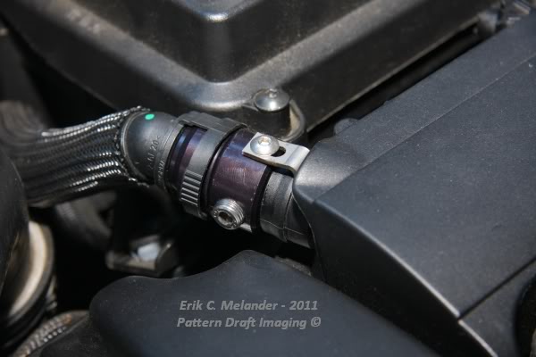
Following the outlined details from BSH's website, I started with assembling the billet boost tap housing and fitted the O-rings and the block-off plug. To ensure the seal of the plug, I lightly smeared a layer of RTV silicone on the threads and then snugged it down. Currently at the time of installation, I wasn't planning to run a boost gauge, so I attempted to fit in both of the 1/8"NPT vacuum port plugs. With the billet housing anodized after being fabricated, I could not get the vacuum plugs to properly thread. So bad, that I had to locate a 1/8" thread tap and re-tap and clean the threads to accept the plugs. After cleaning, again I smeared on some RTV silicone and installed the plugs. Fitment of the housing into the passenger side PCV spout was spot on and double o-ring seal was excellent. However the retaining hardware clip needed a quick sanding after being lasered out of stainless; it had some sharp edges and splinters that needed to be removed for installation and fit + finish.
Ratings (out of 10 scale: 1-poor, 10-perfect / learning: 1-hard / 10-easy)
Installation Time: 7
* very simple to orient direction; however had to clean up threads on housing
Learning Experience: 8
* simple, effective - however, BSH should include comprehensive paper directions within the box
Performance: 10
* perfectly blocks off the passenger side PCV spout and with no blow-by
Bang-for-the-Buck: 6
* it's seems expensive for a lathed / milled piece of aluminum; but that's because I think some of the quality control checks were lacking. If everything was simple from right out the box, this would have seen a higher rating
Overall Rating: 8.5
* properly fits within the engine bay and appreciate the black finish to make it not standout
Review (Competition Oil Catch Can):
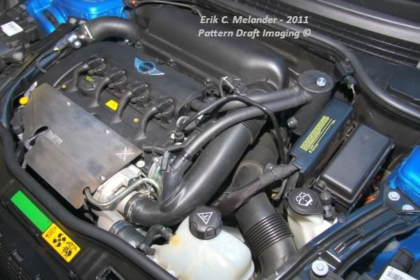
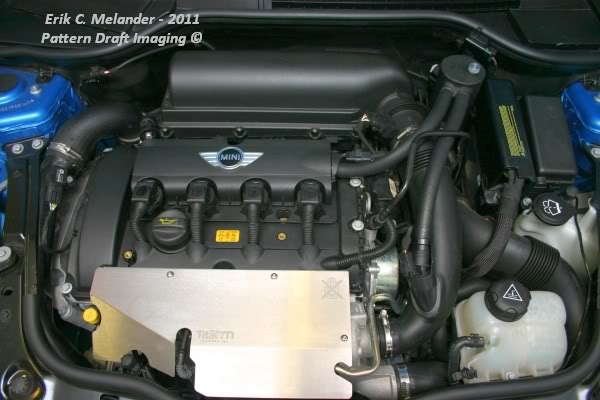
The can assembly was similar in terms of assembling the billet tap barbs that attach to the driver side PCV spout and the turbo inlet pipe; fit both with the proper o-rings. Similar to the boost tap, no directions were provided in the box, printed them off to have a "quick cheat sheet" near me if thing went south. After removing the OEM PCV tube from the engine, I inserted the adapter barbs. The driver spout adapter went in without a hitch; however the turbo inlet tube adapter needed some serious grunt to put in. The o-rings on the inlet tube adapter were a little to fat and the plastic inlet tube actually cut into the o-rings slicing a small tangental piece. The seal still held after inserting, but the adapter has a small loose-feeling 'wiggle' to it.
Now, my 2009 model has the available security system with the hood latch sensor mounted to the same mounting place as the catch can. Instead of mounting underneath the mounting tab or underneath the sensor (which would have improperly raised the sensor above the weather sealing), I made a replacement bracket out of 18 guage 304 stainless. Similar to the catch can and the OEM sensor bracket, I cleaned and painted the L-bracket and the new sensor bracket so that would not stand out in the engine bay.


Once the can was mounted, the plastic tab of the cowl didn't seem to happy about the excess weight. The can kind of 'flapped' around and made me hesitant to continue, as I thought surely a bump impact from the susension may crack this tab off, dropping the can. But I pressed on and installed the push lock tubing. I measured, aligned and cut the tubing to my desired lengths. After installing, the can flopping sensation went away; great! However, now my eyes were distracted by the white imprinted lettering on the hose. I removed the hoses from their connections and wiped them down with acetone; within seconds the white lettering was removed leaving just a clean tube. Re-installed and was content and the appearance.
Ratings (out of 10 scale: 1-poor, 10-perfect / learning: 1-hard / 10-easy)
Installation Time: 8
* BSH estimates an hour, I spent just under 45 mins.
Learning Experience: 7
* complete kit; great craftsmenship, but again BSH should include comprehensive paper directions within the box
Performance: 9
* after just a quick drive, I already saw oil collecting in the can
Bang-for-the-Buck: 8
* fit and finish of the can is higher than the boost tap assembly; love the wrinkle finish and the detail work
Overall Rating: 9
* the final result would pass by even the most picky of on-lookers; assuming you put in some elbow grease to clean up some loose ends.
Follow up with how-much oil is pulled will be recorded and posted by the end of summer.
- Erik
Background:
There's been heavy discussion on the N14's positive crankcase ventilation (PCV) system and how it seriously influences the result of carbon build-up on the intake valves of the cylinder head. I wanted to systematically test and see if the amount of oil being pulled from the valve cover was based on engine design, or driver technique.
- Disclaimer -
As always, I am NOT responsible for the careless acts of others when using this DIY as a reference.
Basically all of you are smart enough not to stab yourself, the very important wiring, or the paint on your car.
Be careful and take any precautionary measures that you deem necessary for completing this task.
Supplies:
* BSH Spped Shop - Competition Oil Catch Can (#20201011) assembly kit
* BSH Speed Shop - Direct Dual Boost Tap (#20201102)
* locktite or hightemp RTV silicone
Review (Direct Dual Boost Tap):
Following the outlined details from BSH's website, I started with assembling the billet boost tap housing and fitted the O-rings and the block-off plug. To ensure the seal of the plug, I lightly smeared a layer of RTV silicone on the threads and then snugged it down. Currently at the time of installation, I wasn't planning to run a boost gauge, so I attempted to fit in both of the 1/8"NPT vacuum port plugs. With the billet housing anodized after being fabricated, I could not get the vacuum plugs to properly thread. So bad, that I had to locate a 1/8" thread tap and re-tap and clean the threads to accept the plugs. After cleaning, again I smeared on some RTV silicone and installed the plugs. Fitment of the housing into the passenger side PCV spout was spot on and double o-ring seal was excellent. However the retaining hardware clip needed a quick sanding after being lasered out of stainless; it had some sharp edges and splinters that needed to be removed for installation and fit + finish.
Ratings (out of 10 scale: 1-poor, 10-perfect / learning: 1-hard / 10-easy)
Installation Time: 7
* very simple to orient direction; however had to clean up threads on housing
Learning Experience: 8
* simple, effective - however, BSH should include comprehensive paper directions within the box
Performance: 10
* perfectly blocks off the passenger side PCV spout and with no blow-by
Bang-for-the-Buck: 6
* it's seems expensive for a lathed / milled piece of aluminum; but that's because I think some of the quality control checks were lacking. If everything was simple from right out the box, this would have seen a higher rating
Overall Rating: 8.5
* properly fits within the engine bay and appreciate the black finish to make it not standout
Review (Competition Oil Catch Can):
The can assembly was similar in terms of assembling the billet tap barbs that attach to the driver side PCV spout and the turbo inlet pipe; fit both with the proper o-rings. Similar to the boost tap, no directions were provided in the box, printed them off to have a "quick cheat sheet" near me if thing went south. After removing the OEM PCV tube from the engine, I inserted the adapter barbs. The driver spout adapter went in without a hitch; however the turbo inlet tube adapter needed some serious grunt to put in. The o-rings on the inlet tube adapter were a little to fat and the plastic inlet tube actually cut into the o-rings slicing a small tangental piece. The seal still held after inserting, but the adapter has a small loose-feeling 'wiggle' to it.
Now, my 2009 model has the available security system with the hood latch sensor mounted to the same mounting place as the catch can. Instead of mounting underneath the mounting tab or underneath the sensor (which would have improperly raised the sensor above the weather sealing), I made a replacement bracket out of 18 guage 304 stainless. Similar to the catch can and the OEM sensor bracket, I cleaned and painted the L-bracket and the new sensor bracket so that would not stand out in the engine bay.
Once the can was mounted, the plastic tab of the cowl didn't seem to happy about the excess weight. The can kind of 'flapped' around and made me hesitant to continue, as I thought surely a bump impact from the susension may crack this tab off, dropping the can. But I pressed on and installed the push lock tubing. I measured, aligned and cut the tubing to my desired lengths. After installing, the can flopping sensation went away; great! However, now my eyes were distracted by the white imprinted lettering on the hose. I removed the hoses from their connections and wiped them down with acetone; within seconds the white lettering was removed leaving just a clean tube. Re-installed and was content and the appearance.
Ratings (out of 10 scale: 1-poor, 10-perfect / learning: 1-hard / 10-easy)
Installation Time: 8
* BSH estimates an hour, I spent just under 45 mins.
Learning Experience: 7
* complete kit; great craftsmenship, but again BSH should include comprehensive paper directions within the box
Performance: 9
* after just a quick drive, I already saw oil collecting in the can
Bang-for-the-Buck: 8
* fit and finish of the can is higher than the boost tap assembly; love the wrinkle finish and the detail work
Overall Rating: 9
* the final result would pass by even the most picky of on-lookers; assuming you put in some elbow grease to clean up some loose ends.
Follow up with how-much oil is pulled will be recorded and posted by the end of summer.
- Erik
Last edited by bluefox280; 08-09-2011 at 08:52 PM.

#470
07-28-2011, 11:21 AM

1st Gear
Join Date: Jun 2008
Location: South Pasadena, CA
Posts: 50
Likes: 0
Received 0 Likes
on
0 Posts
Erik,
I'm starting my catch can and boost tap install this weekend, so thanks for the write-up. Like you, I'm using the boost tap to close the other PCV port. You connected the existing hose to the boost tap, but since the tap is now plugged, nothing goes into the hose, correct? Where does the other end of the hose go? And could it be removed?
Sush@BSH: Why aren't installation instructions included with either the catch can or the boost tap? With all the effort BSH obviously put into developing the can & the tap, there's got to be a reason for not including instructions.
#471
07-28-2011, 12:01 PM
Erik,
I'm starting my catch can and boost tap install this weekend, so thanks for the write-up. Like you, I'm using the boost tap to close the other PCV port. You connected the existing hose to the boost tap, but since the tap is now plugged, nothing goes into the hose, correct? Where does the other end of the hose go? And could it be removed?
Sush@BSH: Why aren't installation instructions included with either the catch can or the boost tap? With all the effort BSH obviously put into developing the can & the tap, there's got to be a reason for not including instructions.
I'm starting my catch can and boost tap install this weekend, so thanks for the write-up. Like you, I'm using the boost tap to close the other PCV port. You connected the existing hose to the boost tap, but since the tap is now plugged, nothing goes into the hose, correct? Where does the other end of the hose go? And could it be removed?
Sush@BSH: Why aren't installation instructions included with either the catch can or the boost tap? With all the effort BSH obviously put into developing the can & the tap, there's got to be a reason for not including instructions.
Dave
#472
07-28-2011, 12:39 PM
And as DneprDave correctly put, the other end of the hose is already attached to the intake manifold.
It's technically a "dead" volume space if you're not hooking up a gauge.
Yes, the hose could be removed thanks to czar's detailed help.
But you wouldn't use the boost tap; instead there are OEM cover plugs for the valve cover and intake manifold.
- Erik
#473
07-29-2011, 09:07 AM
1st Gear
Join Date: Jun 2008
Location: South Pasadena, CA
Posts: 50
Likes: 0
Received 0 Likes
on
0 Posts
Erik,
I checked the plugs for the tap I received and, like yours, the threads are tight. I can only get about one complete turn. I noticed on your pictures that your plugs didn't screw all the way flush to the tap. I don't have access to a tap/dye set so I'll look for a heavy bolt and see if I can clear out the threads the old fashion way.
Is there much pressure against the plugs? Will loctite create an air tight seal?
#474
07-30-2011, 11:30 AM
Garb local 1/8 NPT tap from any local hardware store.
Originally Posted by Chilao;
Is there much pressure against the plugs? Will loctite create an air tight seal?
Locktite will work, but I preferred the RTV silicone so I could easily remove the plugs later for accessories.
- Erik
#475
08-09-2011, 08:21 PM
2nd Gear
Join Date: Mar 2009
Location: Washington
Posts: 98
Likes: 0
Received 0 Likes
on
0 Posts
This is the results after 4 weeks. I am curious, the oil is on top and I figure water on the bottom, what the heck is the creamy gunk in the middle? Is that dirt build up?