
Drivetrain Another legitimate Oil Catch Can question...
#101
 02-18-2015, 12:03 PM


coke
indimanic, if the engine has over 20-30k miles on it, the valve guides are already worn from the deposits on the valve stems cycling into the guide, so oil WILL ingest from passing the valve seals and guides and will cause some coking. We are seeing excess valve guide tolerances at as low as 20k miles and that has something we haven't seen in the past 20-25 years with port injection. So that would be a path even with a deleted PCV system.
Yes I know. I stated that earlier in the post.
In fact, with my first set up, it's the only source or carbon build up.
I will say that after 8k miles or so I saw build up again. I used Sea Foam and re-inspected, the valve were clean again..
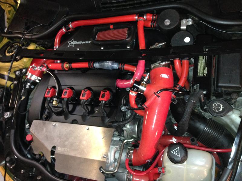
This is my latest set up; 2 cans and 3 vents from CC. Vacuum on cans under idle/light accel then one way cut off valve under boost but vacuum from turbo inlet.

#103
02-22-2015, 08:05 AM

1st Gear
Join Date: Feb 2015
Location: Indpls.
Posts: 44
Likes: 0
Received 0 Likes
on
0 Posts
#104
02-24-2015, 06:48 AM

Catch can I live in Tampa And I'm available
Excellent paper on most all relating to the PCV system and it's functions! This diagram I took from it as it lays out each component:
Component Function
Ventilation Line This is the hose or tube that allows crankcase air to exit the crankcase. On some engines,
there are multiple lines that perform this function. Typically, this type of line will exit near
the top of the engine (valve cover, for example) and will have the PCV Valve in the line. It is
often connected back to a port on the intake manifold.
Makeup Air Line This is the hose or tube that lets fresh air come into the engine as crankcase air is exiting
through the Ventilation Line. On many vehicles, the makeup air line runs from the top of the
engine (valve cover, for example) to the base of the air filter or airbox.
PCV Valve The PCV valve is the most misunderstood part of the CCV system in my experience. This
valve has two primary goals: to regulate the volume of CCV air flow, and to be cheap. I put
the second goal there because it is true, and because it is the cause for some compromise
on the first goal.
Vacuum Source For the system to function properly there must be some source of vacuum to �pull� on the
Ventilation Line. In many cases, the vacuum source is a tap off of the intake manifold (which
This covers a naturally aspirated application, but the mini's I see are turbo charged, and by plugging the dirty side (the upper left corner in the picture) there is no evacuation taking place at idle, deceleration, or non-boost cruising. And then all the oil containing blow by vapors are traveling backwards, out the clean, or fresh side. So, the picture shows clean and dirty running to one can....this will stop most oil ingestion, but at the sacrifice of engine life as almost all the damaging combustion by-products are left in the crankcase to accumulate.
As in the Arrington paper (again, great paper), they do a great job of describing what each component of a PCV system does, and how it does it....so defeating evacuation defeats the constant removal of the compounds entering (the paper misses sulfuric acid and water vapor as well as abrasive carbon and soot particles) before they have a chance to settle and accumulate in the crankcase.
So, the proper fix for the mini as shown in the picture, is a dual valve can system that has dual outlets and checkvalves flowing away from the can inline on these outlets. The upper right corner would go to the inlet (center) of a dual valve can as this shows:
(this is a turbo 4 cylinder for the new Caddy ATS, but same principal:
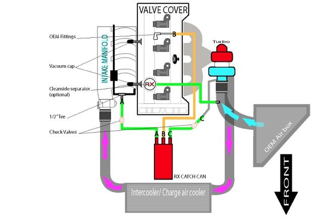
And a picture of a dual valve can showing the center inlet, outer outlets:
So, upper left corner from valve cover to center of can (inlet of foul/dirty vapors), one outlet with checkvalve flowing away from can to prevent any boost from entering the intake manifold when turbo builds boost and intake manifold vacuum is no longer present to provide evacuation, second outlet with checkvalve flowing away from the can connects to a barb you install right at the turbo inlet. You want to be as close as possible to realize the greatest suction while in boost to continue evacuating, the OEM connection is close enough for the turbo side of the fresh/clean side, the ATS diagram shows that GM has a suction port/circuit already built into the turbo inlet side for this. Then on the clean.fresh side (other end of valve cover that runs to the turbo intake tube) needs to be replaced with a clean side separator that will then connect to a -8 3/8" NPT barb you add just downstream from the MAF sensor. This maintains MAF metered air so your short term fuel trims don't go nuts trying to adapt to the un-metered air the open vented cans allow, and it maintains a closed emissions compliant system in all 49 States (CA needs CARB cert components). So, here is how the final solution will flow:
Filtered, MAF metered fresh air enters the new barb added to the cold air intake tube, runs through the clean side separator (replaces oil fill cap, and the valve cover factory barb is capped) where any oil back flow is caught, this travels through the crankcase flushing the dirty/foul vapors out and replaces them with clean filtered air. The outgoing foul/dirty vapors then run through the oil separating can, and then depending on if in boost, or if non-boost, either the intake manifold vacuum evacuates/sucks then scrubbed vapors out into the intake manifold directly, or if in-boost, the turbo inlet suction pulls it in that path where it is then pushed into the intake manifold where it can pass the valves with no compounds to coke, or bake onto the valves.
Hope this helps.
Hey, anyone with a Mini near Tampa/Sarasota that could come in for a few hours and I will install a system and video it all for others. Wont charge any labor, and then we can have a narrated video for all here.
PM me for details and to confirm.
Component Function
Ventilation Line This is the hose or tube that allows crankcase air to exit the crankcase. On some engines,
there are multiple lines that perform this function. Typically, this type of line will exit near
the top of the engine (valve cover, for example) and will have the PCV Valve in the line. It is
often connected back to a port on the intake manifold.
Makeup Air Line This is the hose or tube that lets fresh air come into the engine as crankcase air is exiting
through the Ventilation Line. On many vehicles, the makeup air line runs from the top of the
engine (valve cover, for example) to the base of the air filter or airbox.
PCV Valve The PCV valve is the most misunderstood part of the CCV system in my experience. This
valve has two primary goals: to regulate the volume of CCV air flow, and to be cheap. I put
the second goal there because it is true, and because it is the cause for some compromise
on the first goal.
Vacuum Source For the system to function properly there must be some source of vacuum to �pull� on the
Ventilation Line. In many cases, the vacuum source is a tap off of the intake manifold (which
This covers a naturally aspirated application, but the mini's I see are turbo charged, and by plugging the dirty side (the upper left corner in the picture) there is no evacuation taking place at idle, deceleration, or non-boost cruising. And then all the oil containing blow by vapors are traveling backwards, out the clean, or fresh side. So, the picture shows clean and dirty running to one can....this will stop most oil ingestion, but at the sacrifice of engine life as almost all the damaging combustion by-products are left in the crankcase to accumulate.
As in the Arrington paper (again, great paper), they do a great job of describing what each component of a PCV system does, and how it does it....so defeating evacuation defeats the constant removal of the compounds entering (the paper misses sulfuric acid and water vapor as well as abrasive carbon and soot particles) before they have a chance to settle and accumulate in the crankcase.
So, the proper fix for the mini as shown in the picture, is a dual valve can system that has dual outlets and checkvalves flowing away from the can inline on these outlets. The upper right corner would go to the inlet (center) of a dual valve can as this shows:
(this is a turbo 4 cylinder for the new Caddy ATS, but same principal:
And a picture of a dual valve can showing the center inlet, outer outlets:
So, upper left corner from valve cover to center of can (inlet of foul/dirty vapors), one outlet with checkvalve flowing away from can to prevent any boost from entering the intake manifold when turbo builds boost and intake manifold vacuum is no longer present to provide evacuation, second outlet with checkvalve flowing away from the can connects to a barb you install right at the turbo inlet. You want to be as close as possible to realize the greatest suction while in boost to continue evacuating, the OEM connection is close enough for the turbo side of the fresh/clean side, the ATS diagram shows that GM has a suction port/circuit already built into the turbo inlet side for this. Then on the clean.fresh side (other end of valve cover that runs to the turbo intake tube) needs to be replaced with a clean side separator that will then connect to a -8 3/8" NPT barb you add just downstream from the MAF sensor. This maintains MAF metered air so your short term fuel trims don't go nuts trying to adapt to the un-metered air the open vented cans allow, and it maintains a closed emissions compliant system in all 49 States (CA needs CARB cert components). So, here is how the final solution will flow:
Filtered, MAF metered fresh air enters the new barb added to the cold air intake tube, runs through the clean side separator (replaces oil fill cap, and the valve cover factory barb is capped) where any oil back flow is caught, this travels through the crankcase flushing the dirty/foul vapors out and replaces them with clean filtered air. The outgoing foul/dirty vapors then run through the oil separating can, and then depending on if in boost, or if non-boost, either the intake manifold vacuum evacuates/sucks then scrubbed vapors out into the intake manifold directly, or if in-boost, the turbo inlet suction pulls it in that path where it is then pushed into the intake manifold where it can pass the valves with no compounds to coke, or bake onto the valves.
Hope this helps.
Hey, anyone with a Mini near Tampa/Sarasota that could come in for a few hours and I will install a system and video it all for others. Wont charge any labor, and then we can have a narrated video for all here.
PM me for details and to confirm.
#105
02-24-2015, 02:21 PM

2nd Gear
PM me and we will get you right down.
indimanic, I re-read your post...you are venting? That defeats all evacuation of the damaging combustion by-products allowing them to accumulate in the crankcase and the oil drastically shortening engine life (unless like many racers, the oil is changed every event/race, but that is expensive). You mus have proper evacuation or your only releasing pressure and some of the vapors.
indimanic, I re-read your post...you are venting? That defeats all evacuation of the damaging combustion by-products allowing them to accumulate in the crankcase and the oil drastically shortening engine life (unless like many racers, the oil is changed every event/race, but that is expensive). You mus have proper evacuation or your only releasing pressure and some of the vapors.
#106
02-24-2015, 03:18 PM

#107
02-27-2015, 08:49 AM
2nd Gear
Good question though!!
#108
02-28-2015, 06:41 AM
1st Gear
Join Date: Feb 2015
Location: Indpls.
Posts: 44
Likes: 0
Received 0 Likes
on
0 Posts

#110
03-01-2015, 07:45 AM
see #8 posting
see #8 posting
doesn't take a rocket scientist to see..... if that goes in, it makes buildup
https://www.northamericanmotoring.co...catch-can.html
doesn't take a rocket scientist to see..... if that goes in, it makes buildup
https://www.northamericanmotoring.co...catch-can.html
#112
03-01-2015, 08:05 AM

#114
03-01-2015, 09:13 AM
Venting to air is just OK
The DME wants to see some additional air that comes from the crank case.
Additionally one loses vacuum to assist in scavenging the crank case.
With my setup you get 2 cans, in serial both getting vacuum, I use a RIPP high pressure one way valve that takes the stress off the cheap and under designed built in unit in the valve cover (the added boost causes the valve cover and the PCV valve to fail) I also have the additional vent source from the oil cap (the highest point in the engine) So I have the 3 crank vent all going to 2 cans, under vacuum under idle, low to mid throttle then, under boost the vacuum comes from the turbo inlet, still drawing through all 3 sources and the 2 cans. Further my A/F and fuel trim is not taxed by venting to atmoshphere AND it's environmentally friendlyI
Its ideal really. I added a ball valve so I can control the amount of vacuum.
Unfortunately one will still get carbon build up from oil and normal oil down the intake guides & usual oil vapors that back flow from overlap.
#116
03-01-2015, 12:58 PM
Occ
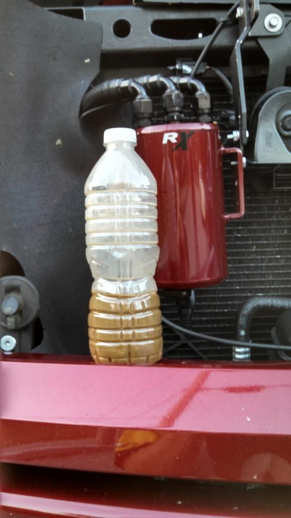
Here's something else I wanted to share. My car's engine has 104k. The last 15 being harsh, high boost & track driven. I hardly burn any oil. I feel the pcv system does such a good job at separating oil that my exhaust bears the proof. This pic is not doctored and the pipes have not been cleaned at all.
I can help anyone make this setup if desired.
I can help anyone make this setup if desired.
#117
03-01-2015, 03:08 PM
Here's something else I wanted to share. My car's engine has 104k. The last 15 being harsh, high boost & track driven. I hardly burn any oil. I feel the pcv system does such a good job at separating oil that my exhaust bears the proof. This pic is not doctored and the pipes have not been cleaned at all.
I can help anyone make this setup if desired.
I can help anyone make this setup if desired.
That's exactly the best situation, keeping the oil and engine very hot like a New York cab. Short trips, cold weather, easy driving is the worst situation.
#118
03-02-2015, 07:03 AM
2nd Gear
Venting to air is just OK
The DME wants to see some additional air that comes from the crank case.
Additionally one loses vacuum to assist in scavenging the crank case.
With my setup you get 2 cans, in serial both getting vacuum, I use a RIPP high pressure one way valve that takes the stress off the cheap and under designed built in unit in the valve cover (the added boost causes the valve cover and the PCV valve to fail) I also have the additional vent source from the oil cap (the highest point in the engine) So I have the 3 crank vent all going to 2 cans, under vacuum under idle, low to mid throttle then, under boost the vacuum comes from the turbo inlet, still drawing through all 3 sources and the 2 cans. Further my A/F and fuel trim is not taxed by venting to atmoshphere AND it's environmentally friendlyI
Its ideal really. I added a ball valve so I can control the amount of vacuum.
Unfortunately one will still get carbon build up from oil and normal oil down the intake guides & usual oil vapors that back flow from overlap.
The DME wants to see some additional air that comes from the crank case.
Additionally one loses vacuum to assist in scavenging the crank case.
With my setup you get 2 cans, in serial both getting vacuum, I use a RIPP high pressure one way valve that takes the stress off the cheap and under designed built in unit in the valve cover (the added boost causes the valve cover and the PCV valve to fail) I also have the additional vent source from the oil cap (the highest point in the engine) So I have the 3 crank vent all going to 2 cans, under vacuum under idle, low to mid throttle then, under boost the vacuum comes from the turbo inlet, still drawing through all 3 sources and the 2 cans. Further my A/F and fuel trim is not taxed by venting to atmoshphere AND it's environmentally friendlyI
Its ideal really. I added a ball valve so I can control the amount of vacuum.
Unfortunately one will still get carbon build up from oil and normal oil down the intake guides & usual oil vapors that back flow from overlap.
#119
03-02-2015, 07:53 AM
Actually JPMM my coolant temp stays at 180 all day long. I drive it on the street too. The tune accomplished this.
Although I do not have an oil temp gauge whereas in the past on other cars I did, the only thing that caused elevated oil temps was stop and go traffic. ON the track the temps stayed close to normal freeway driving temps
My A/F is actually slightly rich 14.3 idle 12.5 load and 10.9 WOT.
I burn next to no oil; 1/4 qt every 3-4k.
I really cannot understand why though with 104k miles and the valve train is making some serious noise (not t-chain)
This motor should go soon.
#120
03-02-2015, 07:58 AM

Former Vendor
Good info in your post. What is your oil pressure at WOT? Have you popped off your valve cover and inspected your chain guides? You might have broken a bit of the guide off. If that's the case, it's a relatively cheap and easy fix.
#121
03-02-2015, 10:13 AM
#122
03-02-2015, 10:53 AM
2nd Gear
I can add to the timing chain issues, and it appears ALL newer engines with the low profile gears and roller chains are wearing prematurely primarily due to the close tolerances involved and the fact that these really need a good FULL synthetic, and not the cheaper syn blends the dealers are using. Any amount of wear and issues arise, where the overhead cams in the past had a higher profile tooth pattern on the gears and could tolerate some slop. Also, if you look closely at the tensioners, the spring is not that strong as they rely on oil pressure to maintain proper tension...and they wear quite quickly when syn blend is used. Even a small amount of wear/open tolerances allows oil to bleed past and this allows them to jump a tooth or so much easier. Now, when the timing set is replaced, there is still the added wear to the followers and other valve train components so indi may be correct in it being valvetrain issue for him at this point. Cam lobe is rare now days, but can still happen.
Aside from this, these engines should go several hundred thousand miles no problem.
Aside from this, these engines should go several hundred thousand miles no problem.
#123
03-02-2015, 11:05 AM
Former Vendor
I hear you, but relying on warranties is risky. If it's a lifter, you'll hear a single tick per engine revolution, versus a clatter of timing equipment, or worn lobes. Typically a single lobe doesn't wear out but all of them do, so, single tick: lifter, multiple clatter: lobes (assuming that your timing chain, tensioner and rails are indeed good).
#124
03-02-2015, 02:01 PM
2nd Gear
I hear you, but relying on warranties is risky. If it's a lifter, you'll hear a single tick per engine revolution, versus a clatter of timing equipment, or worn lobes. Typically a single lobe doesn't wear out but all of them do, so, single tick: lifter, multiple clatter: lobes (assuming that your timing chain, tensioner and rails are indeed good).
Agreed. Unless the bucket or follower fail. Good knowledge Helix!