When you click on links to various merchants on this site and make a purchase, this can result in this site earning a commission. Affiliate programs and affiliations include, but are not limited to, the eBay Partner Network.
finally .... I managed to collect all the necessary items, had long e-mails with Tuner Boost and Indimanic I modified my Saikou Michi twin OCC setup and added an Elite Engineering clean side separator...
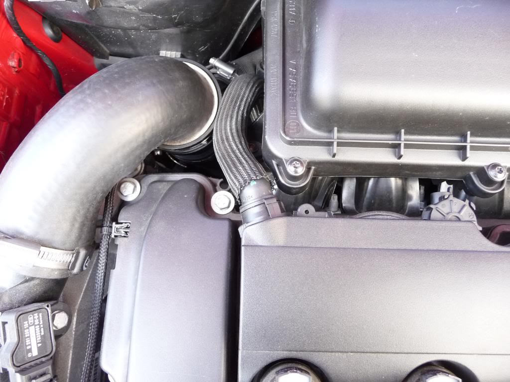
one picture tells 1000ds of words, so this is what it looks like now:
Current setup! Hopefully this is the final one :p
Elite Engineering clean side separator is attached to the 'clean side' of the valve cover
one way check valve added after the 'T' barb, pointing OUT from the CC
one way check valve added after the 'T' barb, pointing OUT from the CC
12mm barb attached to the turbo inlet, valve cover now gets fresh air, eliminates valve cover pressure
Clean side separator
i also blanked the sound/noise generator, this was a 4 USD upgrade, cheapest and greatest
In a nutshell, the twin OCCs are now connected/linked, therefore it filters the dirty side twice prior it goes to the exhaust manifold.
With the help of the one way check valves there is always suction, in case of idle the 'bottom' 1 way valve is open and the other is closed, in case of boost, the 'top' is open and the bottom is closed.
Valve cover is never under pressure, hopefully it'll resolve the oil consumption challenge we all face with.
Unf I was unable to place the clean side separator upwards ... couldn't make the 90 ... so i hope this will be OK as well.
I would be grateful if Tracy could confirm this
again, thanks for your + Indimanic help!! The car runs great, for some reason, i feel i got back some throttle response which was lost somehow ....
So with this set up, since you placed the barb directly into the turbo inlet, this may not be easily possible for those of us with an AEM intake with a metal inlet tube. Or is there another way around that?
So with this set up, since you placed the barb directly into the turbo inlet, this may not be easily possible for those of us with an AEM intake with a metal inlet tube. Or is there another way around that?
Difference between drilling into a metal or drilling into a plastic is nothing.. actually a metal hole can be easily patched in case of need.
I have read the statement several times of people saying " the valve cover now gets fresh air " when taping into the turbo inlet piping ???
Can someone clear the air for me ?
The turbo inlet pipe is under a vacuum from the turbo sucking ?
The OEM valve cover has a check built inside to just let air/gasses flow out of the valve cover ?
Just asking is all
The turbo inlet pipe is under a vacuum from the turbo sucking ?
--- obviously not, then the turbo is under boost, there is no vacuum within the turbo inlet pipe. however there is suction all the time within the oil catch cans
The OEM valve cover has a check built inside to just let air/gasses flow out of the valve cover ?
-- that is true, however i bet you also seem some oil mist around the edge of the your valve cover, which means, it is under pressure..
and yes, the valve cover gets fresh air ALL the time, under boost and under vacuum/idle situation.
with the OEM setup, it only gets fresh air when the car is under idle.
grZack, great set up you have there, i was going to try the rx oil catch can and their system but something happened because they never got back to me after i email them several times.
grZack, great set up you have there, i was going to try the rx oil catch can and their system but something happened because they never got back to me after i email them several times.
THX!!! -- the engine is a bit dirty .. did an oil change as well after 5000 miles also the fittings are not looking gr8, but hey, at least there is a reason why i need to pop up the hood :DDD
check out he Elite Engineering one. Tracy, who designed the clean side separator and this setup owns the idea. He recommended the Elite Engineering one. Same price, quick shipping, fast response and maximum customer satisfaction :D
I am really curious what will I see in the cans as well as whether my exhaust pipes will remain clean. Indimanic has clean exhaust pipes leveraging his parallel setup therefore I cleaned the pipes and will check it regularly.
Wow , I always thought that an engine was sucking air through the air filter into the motor ( a vacuum)
Crazy
Ok, lemme rephrase... With the barb, fresh, filtered air gets into the rocker cover in every case, regardless whether the engine is under vacuum or boost. Is it ok?
The valve/cam cover gets fresh air form the portion of the air intake nearest to the filter it'self. The suction measured near the air filter is far less than measured near the turbo inlet due to the dispersment the filter creates (same CFM of flow, but suction increases as you get closer to the turbo).
So, the air into the valve cover is always clean, filtered, and flowing in. The foul vapors are then evacuated out the opposite end using IM vacuum when not in boost, and turbo inlet suction when in boost. We never want the flow to reverse and flow backwards.
Just got my occ kit the other day, gonna soda blast my valves (again) and see how much 20k miles with no OCC built up on the valves. Hopefully further down the line I can show what 20k with the occ looks like.
The valve cover gets very little fresh air inducted into it; as I recall I tried to blow into both breathers: obviously the pass side is a NO GO for when when under boost.
I recall the drivers side has some restriction. Further, I attached a long hose with a balloon to the drivers side and fed into cockpit. I was surprised to see it slightly collapsed under light throttle and decel which makes some sense. Under load the balloon filled.
Rdndirty is correct in that the turbo inlet side draws CC fumes into the turbo side when under boost. The CC is generally under no to slight pressure under light throttle and builds under higher revs, Depending how worn ones motor is, blow by is now the issue.
When revs are high and one closes the throttle; then a rather large vacuum is created in the CC especially around the intake guides/seals. This causes oil to be sucked down the worn guides/seals. The large vacuum is created by a combination of the throttle being closed, higher revs and the pistons trying to draw air into the cylinder. Instead its sucking oil.
This is why a worn motor smokes under decel. Oil is drawn down the guides and onto the back of the intake valves. Thus, one can never ever completely stop the carbon build up on the back of the intake valves especially as a motor wears.
The intake valves, being much cooler than the exhaust valves causes the oil "condenses" and stick.
Sorry to say. Add meth and now you have a solution.
This is all just a general explanation. Hate to read so much misinformation.
My motor will be apart next week and I am interested in seeing how the meth/H20 did cleaning the valves.
Meth injection helps, but unless it was sprayed constantly to keep the intake valves cool (like old port injection did) and constantly cleaned, it can only do so much. Direct injection intake valves run far hotter than any fuel introduction system since the internal combustion engine was invented as no fuel touches them. Install a system like the true RX and you will eliminate 95% plus of all deposit build-up.
As for the balloon, what you saw is exactly why you do not want to install just any "catchcan". You need one that utilizes two evacuation suction sources like the true RX (not the cheap china knock-off from speedworks or gofastmuscle). This then always pulls suction on the crankcase and no pressure is present in the separator or the crankcase. And yes, if you have worn rings some oil is pulled into the combustion chamber, but that never touches the backsides of the valves.
Now as valve guides wear from these abrasive deposits on the stem being drawn into the guides, this will increase oil getting past the seal and guide and that will add to the issue.
Usually by 20-30k miles valve guides on DI engines are getting worn past acceptable tolerances, unlike port injection that could go 200-300k plus miles w/little to no wear.
I use vacuum from intake manifold on the last outlet of my 2 cans along with 1 way valves and a good ole fashioned pcv valve so there was always some vacuum in the CC system.
Worn rings is what causes all the blowby beyond windage from the crank. We used to see bronze nickle guides worn after 60-70K. Without the lead in fuel, nothing was providing lubrication. I've never taken apart a DI motor to witenss guide wear.I'm looking forward to seeing what the valves & guides look like after running meth for some 4 months. They were pretty clean to start with.
The valve/cam cover gets fresh air form the portion of the air intake nearest to the filter it'self. The suction measured near the air filter is far less than measured near the turbo inlet due to the dispersment the filter creates (same CFM of flow, but suction increases as you get closer to the turbo).
So, the air into the valve cover is always clean, filtered, and flowing in. The foul vapors are then evacuated out the opposite end using IM vacuum when not in boost, and turbo inlet suction when in boost. We never want the flow to reverse and flow backwards.
Hope that helps!
But this "fresh air" talk makes no sense because air can't get IN to the valve cover, it only comes OUT. That's why there is a flap on each end stopping air from coming in. It won't "suck" in air from the other side unless the PCV system is modified or broken.
I agree that this system looks like it would help people more than many of these cans, but this is confusing too many people. There are a couple threads here showing covers that were opened and showing the inner workings of the PCV system if you need a reference of what I'm talking about.
Every engine has a "clean" or "fresh" side, and a "Dirty" or "Foul" side. The fresh/cleanside is the fitting on the valve cover that runs to the main intake air bridge/tube assy. flows both ways. The foul, or dirty side only flows out to prevent boost pressure from entering it has a flap type one-way valve inside for it.
A PCV system has to always have filtered fresh MAF metered (if MAF equipped) incoming air source to make up for and flush the foul contaminant laden vapors being pulled out the opposite portion of the engine. With the Mini, the foul is in the rear on the passenger side of the cam/valve cover. The fresh is on the drivers side portion.
I'm with you alka1ine......
I don't know how "fresh" air goes in when the intake tube is under a vacuum from the turbo sucking air in to the turbo.... then add in the OEM flapper that only lets air out of the valve cover...
maybe a rotometer and a dyno trip is in order......lol
Kind of like the balloon test above ....
besides , if you can get the crankcase under a vacuum you make more horsepower ...
Every engine has a "clean" or "fresh" side, and a "Dirty" or "Foul" side. The fresh/cleanside is the fitting on the valve cover that runs to the main intake air bridge/tube assy. flows both ways. The foul, or dirty side only flows out to prevent boost pressure from entering it has a flap type one-way valve inside for it.
A PCV system has to always have filtered fresh MAF metered (if MAF equipped) incoming air source to make up for and flush the foul contaminant laden vapors being pulled out the opposite portion of the engine. With the Mini, the foul is in the rear on the passenger side of the cam/valve cover. The fresh is on the drivers side portion.
Hope that helps!
Tuner Boost, I have been scratching my head over some of your posts, what you are saying might be correct for some engines, but not for the Mini. For example see here: https://www.northamericanmotoring.co...ml#post4042863
The pictures clearly shows the flow through the N18 valve cover. The port from the valve cover to the intake is one way only.
Here is a scan of the page in the Bentley manual that describes the valve cover and PCV system. They have the A and B labels confused in the text, but if you study it carefully the operation is clear. There is no fresh air supply into the valve cover.
The RX dual valve system provides suction on the crankcase at all times. It uses intake manifold vacuum for non-boost evacuation/suction and turbo inlet suction for in boost. This way there is never pressure in the crankcase.
The Bently manual is a bit incomplete, and here is a animation to better show how all PCV systems have a fresh and a foul (clean and dirty) side to them. W/out this flushing and evacuation function, all the damaging combustion by-products would be staying in the crankcase and accumulating wearing all internal parts rapidly as was the case pre 1960's when the PCV system was mandated:
The one way flap valve located at the passenger side rear of the valve cover only flows out, this is the dirty or foul side. It closes to prevent boost pressure from the intake manifold from entering the crankcase. The other fitting towards the drivers side is the clean, or fresh side of the PCV system where the air, filtered by the main air filter, enters to make up for what is evacuated, or sucked out the passenger side foul outlet. The flaw is when the engine is making boost, and the flapper valve closes on the dirty side, then no evacuation is taking place, and crankcase pressure builds until it reaches the point of pushing "out the in" and these raw oil laden vapors then are forced into the inlet for the turbo. This is a direct path of oil and other contaminants directly into the turbo inlet and further the intake manifold and the intake valves.
By moving the OEM Clean, or fresh side to closer to the main air filter, we accomplish 2 things. We now have the fresh incoming air entering from closer to the main air filter so far less actual vacuum, or suction is present at that location (the closer to the filter, the more dispersion, the less actual measurable suction in inches). We then move the secondary outlet from the main oil separator (dual valve can) to the fitting at the turbo inlet, so no matter what mode the engine is in, boost or non-boost, the crankcase is always evacuating. This suction present at all times on the crankcase accomplishes several things. First, more power as the pistons are not suffering the parasitic loss from fighting pressure on the down stroke. Second, the piston rings will remain more stable, preventing "ring flutter" at high RPM's and this creates a better seal between piston/rings/cylinder wall. Less blow-by, and more power. Third, the crankcase is now evacuating the damaging compounds that enter as a result of blow-by before they have a chance to settle and mix with the oil. Once these mix with the oil, most are there to stay and increase wear (70% of internal engine wear is from abrasive particles smaller than the 15 microns the oil filter can trap down to) until the oil is drained and changed.
Oil stays cleaner, engine life is increased as wear is decreased, and as the RX system is 95% plus effective at trapping all the damaging compounds that cause the intake valve coking (more than oil causes this) you have greatly improved over the OEM system and still retained an emissions compliant PCV system. There will always be a small amount of deposits formation due to the EGR emulation of the variable cam timing and the overlap present, but that is tiny in comparison.
Now, look at the many systems that delete or defeat these critical functions. They result in ALL the contaminates and damaging compound entering and remaining in the crankcase to accumulate and increase wear. They allow crankcase pressure to ALWAYS be present. If they vent or have a breather, they are also introducing un-metered air messing with fuel trims as well as illegal in all 50 States for street use.
These pictures will help understand as well:
First, this shows the foul, or dirty side of the Mini PCV system:
This is where the foul, or oil and damaging compound vapors are pulled from the crankcase. To demonstrate, at idle, simply disconnect the opposite hose (the clean or fresh) from by the turbo and feel the end of it. You can feel the suction as it pulls in the filtered fresh air from the main intake air bridge tube (or would be if connected).
Here is a picture of the clean/fresh side of the PCV system:
Lower right corner of valve cover (differs between years slightly). We move that to the cleanside separator and it now sucks in fresh air from close to the main air filter.
Here is what you see when you take off the main inlet tube and see how the oil is entering the turbo inlet as the PCV is stock.
So, follow this video (yes, it needs updated to be better in detail and instructions).
So, what none of the others do, is to improve the evacuation functions to evacuate at all times. Single or dual cans, you never want pressure in the crankcase and these systems are the next best thing to a belt driven vacuum pump.
Hope this clarifies some but ask more questions if needed.
The Bently manual is a bit incomplete, and here is a animation to better show how all PCV systems have a fresh and a foul (clean and dirty) side to them. W/out this flushing and evacuation function, all the damaging combustion by-products would be staying in the crankcase and accumulating wearing all internal parts rapidly as was the case pre 1960's when the PCV system was mandated:
That may be the way it works on a Honda or in a random youtube video, but it isn't how it works on the Mini N18.
...The other fitting towards the drivers side is the clean, or fresh side of the PCV system where the air, filtered by the main air filter, enters to make up for what is evacuated, or sucked out the passenger side foul outlet.
This ^ is not correct. I had some time on my hands today so I took off the tube that you assert is the "fresh" or "clean" side of the system. (tube from valve cover to turbo inlet at bottom right of your picture)
I took a picture looking IN to the valve cover where the tube to the inlet connects. There is clearly a one way valve, any flow is only OUT of the valve cover, not in. In one of the videos you linked the installer tries blowing into it, unsuccessfully.
It is really simple. There are two OUTLETS built into the valve cover. One leads to the intake manifold and is active when there is manifold vacuum. On the N14 it is external on the rear passenger side, on the N18 that pathway is internal. (See the post I linked previously that shows the internals of the valve cover.) The second path is active when the intake manifold is at positive pressure, it leads out the driver's side to the turbo inlet and is shown in the pic above. These two ports evacuate any crankcase pressure.
Where does the fresh air come from to make up whatever is evacuated from the crankcase? On the N18 there is a separate line, look this up on realoem.com and it is labeled "Crankcase - Ventilation."
I'm not disagreeing with what you say about the need for a PCV system or its benefits, and I'm not making any judgements on the effectiveness of the RX catch can system. I'm just pointing out how the PCV system on the N18 engine really works. (The N14 is similar, but I'm not going to claim to be an authority on the details since I don't have one.)

 08-24-2015, 11:09 PM