When you click on links to various merchants on this site and make a purchase, this can result in this site earning a commission. Affiliate programs and affiliations include, but are not limited to, the eBay Partner Network.
jumper in sys flows great no bars on gauge (w/ dial adjusting also)
jumper in bar. 6 bars on gauge
S and b light up no other lights on
pulled jumper from mode pump is on and flows with throttle
Other than that I have no flow in regular operation or bars on gauge light up
rechecked all wiring seems fine
on board green led works as it should no other led comes on unless in sys
The only wiring difference I've done from your manual is wired the red line from gray harness directly into battery
anyone have any ideas what's not right?
Last edited by snbder4life; 08-27-2019 at 09:57 AM.
"---pulled the jet and replaced it with a blank"??? Guess I don't understand what's wrong and what you're trying to do. My understanding of "a blank" is it's a plug, allowing no flow.
One last thought --- I didn't connect the fail-safe feature on my HFS4, mainly 'cause I don't have the same turbo features on my big Garrett. System has been working fine for a few years, just probably not as safe as it should be. Maybe disable your fail-safe to see if that fixes your problem --- if the HFS3 has a fail-safe.
So tonight I cut MPs 3 and soldered mps2 I have flow now with thres led still no gauge reading no matter what I do
I also soldered all connections to ensure they were good
running about %80 meth no cooler iat
spray comes at about 8psi boost
anyone have any ideas
Last edited by snbder4life; 08-27-2019 at 07:58 PM.
Just a guess but also check page 20 of the v3.1 manual in regards to IDC pre-scalars for DI. Looks like back jumper should be C to B (good) and the other should be B to A instead of A to A.
You could if you wanted to but honestly with the improvements they made in the v3.1 design I don't think it necessary. With 3.1 they refined the DI portion and still allow you to mix boost and IDC for your threshold. You don't have the same level of adjust-ability between those two (see below) but it should work well in our application. I've never installed the HFS3 just the HFS4, AEM and Boost Cooler 2 units. I went thru the manuals and came up with the following. The first addresses the pre-scaler for the IDC as noted previously.
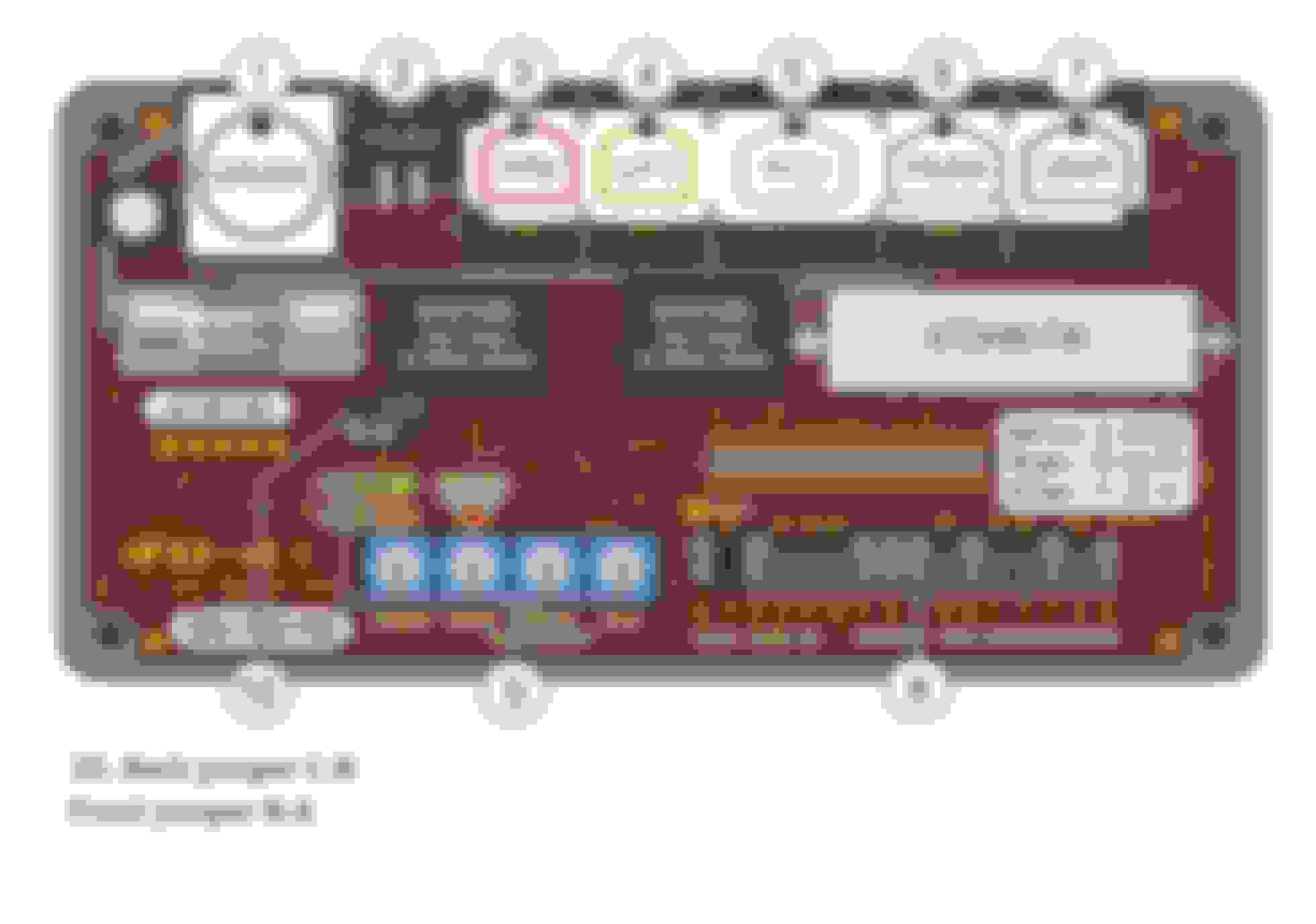
These should be the correct jumper positions on the front. Black dots are default but DR0 goes to DR1 to prevent a CEL during failsafe trigger.
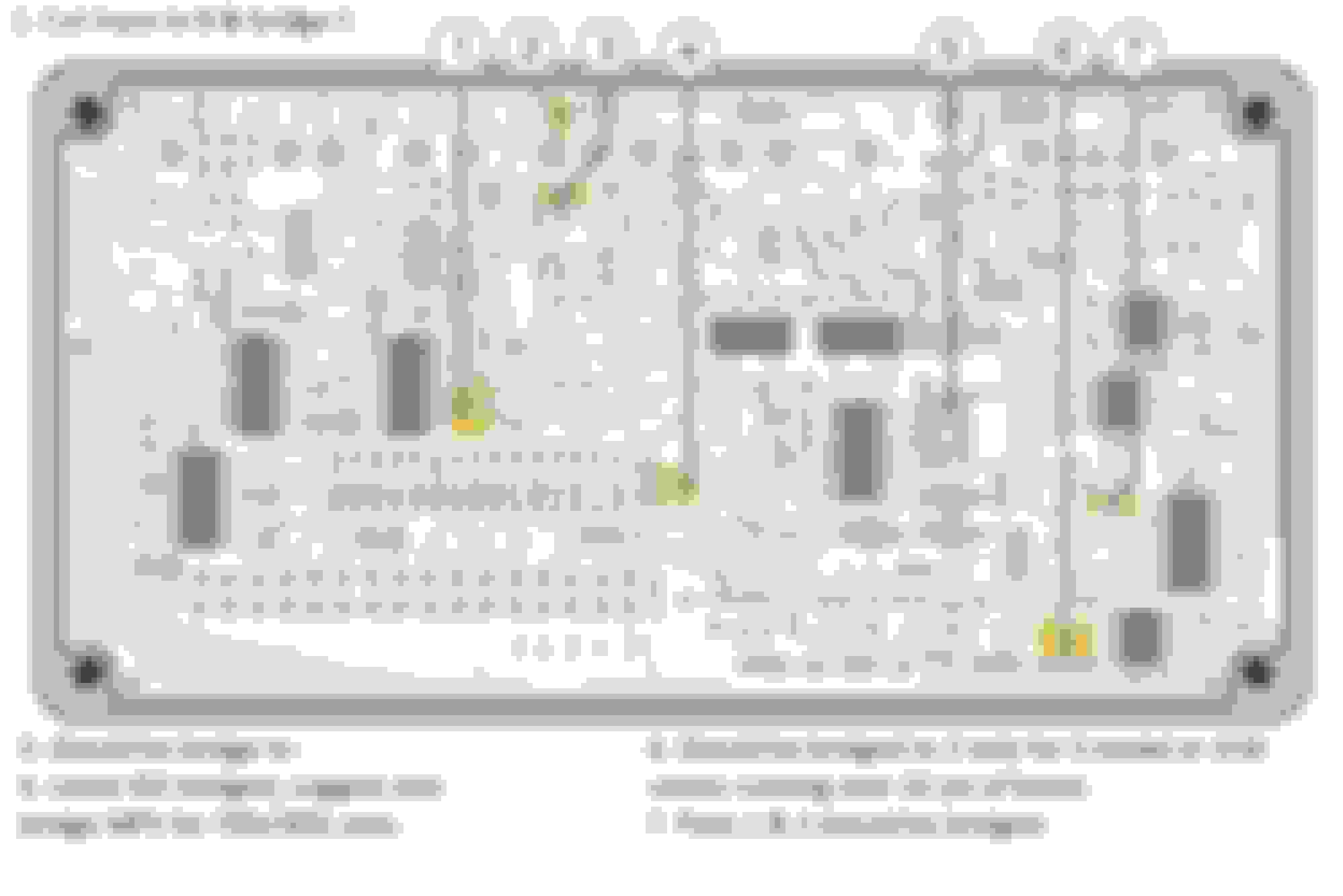
See notes below for the back side. 1. is based on the HFS4 configuration as the HFS3 and HFS4 manuals are silent as to their function.
By bridging IDC and MPS on #4 the system will spray based on 70% IDC signal and 30% Boost.
The S model uses a 2.5 bar MAP sensor and the JCW uses a 3 bar sensor. If not running over 22 psi configure 6 to bridge to 2. Pad two will work with 2 to 2.5 bar sensors and 3 is for 3 to 3.5 bar sensors.
Finally on #7 pads 1 and 2 should be bridged as your running a single nozzle and will be spraying 500 cc/min or less. This effects your flow range and in conjunction with the SC pot on the gauge determines the bars displayed on the gauge.
Hope this helps.
Lou
Here's the Front of the HFS-4. On the right the dashed circles are the default factory setting. I circled current setting with a sharpie.
Here's the back side. Not the prettiest solder joints but I was in a hurry lol.
The voltage output on the MAP sensors is the same 0-5v. The difference is the S sensor output's 4.5v at 250 kPa while the JCW puts out 4.5v at 300 kPa. This is on a linear scale. Both sensors will read accurately to about 4.85v so they will effectively report 1.6 bar and 2.1 bar of boost at sea level baro pressure. With the board configured for 3 bar but being feed voltage by a 2.5 bar sensor the boost will be under reported. You'll still get a signal so it should still work, but its been noted that I'm a bit OCD.
The Aquamist forum is a wealth of information and Richard has been a huge help for many. I noted the Hall effect pick up on your flow sensor is mounted at the 12 o'clock position. I would try rotating it to the 3 o'clock position. I found mine worked best at the 2 o'clock position.
Ty for the guidance I've been searching for the info on the ABC can't find anting on it do you know what it does?
I wrote Richard and it's been a over a week with no reply
I became a member of the forum but can't post in it
I'd recommend a 1.0 nozzle at that power level. Did you tape it to the windshield to verify it's spraying? With a 0.7mm nozzle you should be seeing a drop in inlet temp.

 08-26-2019, 11:40 AM


 It's for the HFS-4 though.


 still no gauge reading no matter what I do