When you click on links to various merchants on this site and make a purchase, this can result in this site earning a commission. Affiliate programs and affiliations include, but are not limited to, the eBay Partner Network.
Hello to everyone, finally found time to make a new thread about the intake manifold that I am working on for a while now.
At this point I would like to point out that this manifold started as an RnD project.
It is a complete out of the box idea-design.
Taking an entire different approach (compared to what is available on the market right now), this project utilizes advance 3D printing, CNC machining and composites technologies .
Initial plan was to develop three different working versions (more on that later) with various technologies, manufacturing methods and materials.
First version is fully 3D printed, manufactured using MJF 3D printing. The material is PA12 Nylon. The objective in this version was to manufacture an intake using only 3D printing.
Second version: Two Way Hybrid. It is a combination of billet aluminum parts and MJF PA12 Nylon. All flanges, brackets and sensor mounts are billet and the core of the manifold is 3D printed. Third version: Three way hybrid. This manifold version is a combination of three materials, carbon fiber, MJF pa12 nylon and billet aluminum (work on progress).
*Can you imagine, that one morning I woke up and made the above plan ? Lunatic ? maybe So far companies that used this technology (MJF 3D Printing) for their intake manifold (as far as I am aware) and manage to have a working product not a demo, are:
Ford Motors (Le Mans 24hr)
Race: Daytona 24hr
Car: Ford Daytona Prototype
3.5 litre EcoBoost Heli racing team (BMW 120d)
Race: Belgian Gentleman Drivers Club (BGDC) and Belcar�s Belgian Endurance Championship
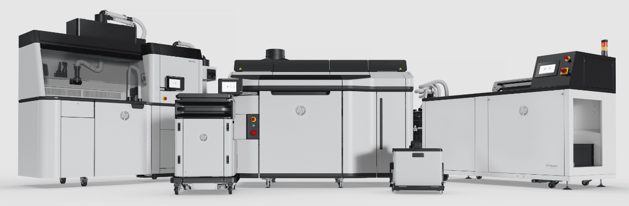
The 3D printer we used is an industrial MJF printer: HP Jet Fusion 5200 (I am in love with this thing ):
It is a whole system that consist of the printer and the cleaning stations. Basic Machine Specs:
Building speedUp to 4115 cm�/hr (251 in�/hr)
Layer thickness 0.08 mm (0.003 in)
Job processing resolution (x, y) 600 dpi
Print resolution (x, y) 1200 dpi
Material: PA12 (which is not 100% PA12, it is actually a recipe of HP).
Why Nylon 12? Nylon 12 is fuel and oil resistant which makes it ideal for this application plus it has a working temperature (not max) of 140 degrees Celsius.
Why it is difficult to make a working MJF printed manifold:
� The print itself, is exceptionally perplexing. Since it is affected by orientation, product shape, thickness, temperature and final application. (don't ask me how I learned all these...).
� PA12 is a flexible material. The manifold cannot be flexible thus the design of the manifold is crucial to avoid any deflection under hard acceleration, extreme heat, or installation. *Designing in a similar way as in injection molding helps a lot.
� The manifold needs to be designed in a way that it can be machined. The part needs machining to create completely flat surfaces where flanges will be used.
� The actual sealing between the manifold and the aluminum parts of the engine bay becomes puzzling due to the flexy nature of this material.
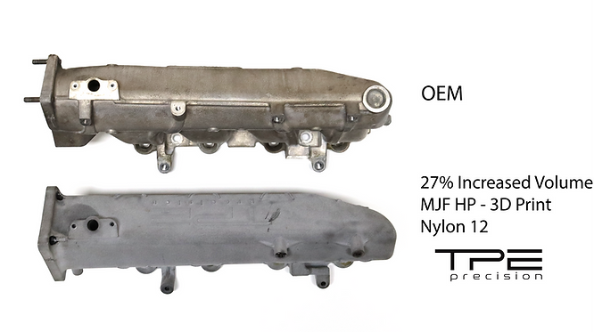
Unfortunately, the OE flanges cannot provide the required sealing. Thus new vitton flanges needed to be made. Above: The manifold on the first cleaning station. The OE unit is an aluminum casted manifold. Casted parts need to have a thickness of at least 5 mm. The OE manifold in the r53 MINI is not an exception with it's thickness varies between 6mm and 8mm!
The TPE Precision version is redesigned with a maximum plenum thickness of just 3mm. Thus the internal volumeis increased,without changing the outside dimensions.
The runners are completely redesigned in order to accommodate the increased internal volume with Increased internal radius, altered angles and increased cross section area (the definition
of a sleeper part )
Version 1 (fully 3d printed):
Working prototype on the photo above vs the original unit.
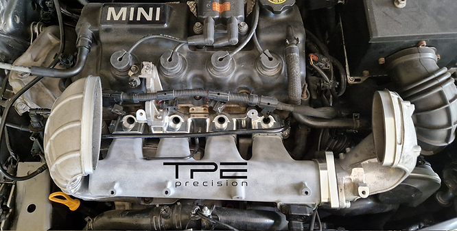
The organic shapes help with the overall stability of the part. They look kind of nice, but I removed them in later revisions, as it was a pain to install the manifold, due to space limitations.
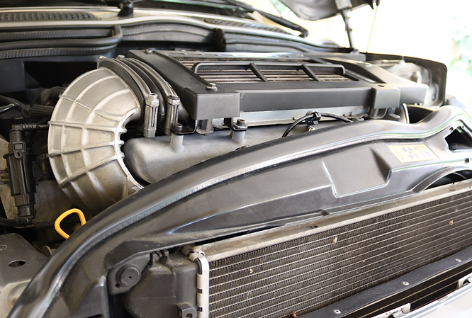
Exactly as the original unit
Plug and play.
Pros of the fully 3d printed manifold:
It is very light! nearly 2kg lighter compare to the original unit.
Every single print can be different, which makes it ideal for bespoke manifolds and ofcourse for testing.
You just print it, clean it and it is ready !
Cons:
It is flexible. It took me 4 working prototypes until I was 100% happy with it.
You can't use the original flanges. I made my own vitton flanges and now everything is good.
You will always need to have small metal inserts, especially in areas like the map sensor and the fuel rail vacuum take off.
Version 2 (hybrid):
At this point, I should say that this is only manifold with this material combination (that I am aware of).
The parts are bonded together, with similar methods manufacturers use in composite monocoques.
For the cylinder flange a 5axis cnc was used.
TPE Precision 2-way hybrid manifold. For me at least, it is like a jewelry
Pros:
I mean just look at it !
You can use the original flanges.
Cons:
The CAM of the billet parts need to be changed every time you have a bespoke manifold. Which drastically increase cost.
Bonding...
It takes time to bond the parts together plus you need ovens. The bond itself is extremely expensive.
If a mistake happens during the bond application or curing you just have to throw away the manifold...
Additionally the bond has a specific number of thermal cycles that can undergo. For racing applications and for the MINI that we do all our testing this is not a problem, as more or less we have a clear picture of the conditions (and hours) the manifold will be used.
For road applications, with many short trips around town .... things are getting complicated.
An engineering exercise?
Yes it is ! Very proud of this manifold because of the gigantic effort from everybody involved on this project and the fact that we have fully printed manifolds that are 100% functional and not just a demo parts.
The power gains are just a byproduct of the above. Power and torque in the whole rpm rage with faster IAT recovery rate
Many people ask me when the product is going to be available for sale.
The two way hybrid seems that it is not going to be for sale as the manufacturing cost is close to the value of the car...
The fully printed manifold (with small metal inserts), seems the best option.
Manufacturing cost is still high but with some design alterations cost is reduced a lot.
In total I have invested in 19 revisions on this version, bringing the cost down a lot! Design-performance wise I am more than happy and I don't plan to change anything.
So bear with me
Extra photos of the manifold: Fully printed manifold. Hybrid version. *The inside is the same in all versions. Early working prototype. Revision 19. This is how the part is, when it is removed from the printer. First cleaning station. Revision 19. Cleaned and ready to put the small metal inserts.
So what do you think?
I would love to hear your comments.
* please excuse all the grammar mistakes, English is not my first language
I run the sneed4speed big intake now. It makes a bit of a difference in flow, but doesn't fix the hot #3 cylinder issue. I track EGTs per cylinder so I can compare how the cylinders are flowing. Higher EGT means the cylinder is flowing better, given equal ignition timing. Cylinders 1&2 have the lowest EGTs and are pretty close. Cylinder 3 is the highest EGT, and requires a bit more fuel to bring the EGT down to the other cylinders. Cylinder 4 is between 1&2 and 3 - right on the edge of needing additional fuel. I can control the fueling per cylinder with the Link ECU.
Alan
p.s. I think this design has a bunch of potential over the sneed4speed big intake - there are big cliffs and discontinuities in the sneed4speed big intake. Sure it has more volume than stock intake, but the internal flow can't be great.
p.p.s. Shorter intake runners will make more peak power, but does it by moving power from the low end of RPM range to upper end. I'm a bit puzzled by your graph - it seems to show the opposite. Maybe the internal runner length difference isn't as big as it looks from the outside in your compare photo above. Or the bigger plenum volume negates the runner length affect?
Beautiful. As an engineer with tons of casting and a small amount of 3D printing experience, this is right up my alley. Thank you for the level of detail in your post.
What type of pressure testing have you done? I'm not familiar with 3D printing nylon whatsoever. How 'airtight' is it?
Ille GLADLY install one of these Manifolds on my highly modified r53 and I could report back my results.. if your willing to make one to sell and for some real world testing.. I love testing parts on my car and seeing their results. Though it currently has a sneed4speed Manifold that's I finished porting out so itm looking for even more volume than that and larger ports yet..
I run the sneed4speed big intake now. It makes a bit of a difference in flow, but doesn't fix the hot #3 cylinder issue. I track EGTs per cylinder so I can compare how the cylinders are flowing. Higher EGT means the cylinder is flowing better, given equal ignition timing. Cylinders 1&2 have the lowest EGTs and are pretty close. Cylinder 3 is the highest EGT, and requires a bit more fuel to bring the EGT down to the other cylinders. Cylinder 4 is between 1&2 and 3 - right on the edge of needing additional fuel. I can control the fueling per cylinder with the Link ECU.
Alan
p.s. I think this design has a bunch of potential over the sneed4speed big intake - there are big cliffs and discontinuities in the sneed4speed big intake. Sure it has more volume than stock intake, but the internal flow can't be great.
p.p.s. Shorter intake runners will make more peak power, but does it by moving power from the low end of RPM range to upper end. I'm a bit puzzled by your graph - it seems to show the opposite. Maybe the internal runner length difference isn't as big as it looks from the outside in your compare photo above. Or the bigger plenum volume negates the runner length affect?
The tune for the 5500 to 7000 rpm range is not finished. We had AFR of 9.5 which is way too rich.
So we expect different results when the tune is done.
It is something that needs to be done in the near future.
Beautiful. As an engineer with tons of casting and a small amount of 3D printing experience, this is right up my alley. Thank you for the level of detail in your post.
What type of pressure testing have you done? I'm not familiar with 3D printing nylon whatsoever. How 'airtight' is it?
Thank you
So far the manifold is tested on a M45 car (my car) and a TVS 900 charger.
There is no problem with Nylon, it is airtight. The only problem that I encountered, were the two flanges.
The original metallic flanges would not seal properly even after I did resurface-flatten the manifold. That's mainly due to the flexy nature of the material. Even a 0.1mm-02mm tolerance difference would create sealing problems.
The solution that seems to work very good so far is bespoke Vitton flanges. 2D drawings - Cylinder head and intercooler horn flanges.
Vitton flanges for Cooper S original cylinder head.
These flanges are cut via water jet.
I still have to do some small changes. So the next revision will have new updated flanges, that will match 100% the cylinder head profile.
With that said, it seems like that the final solution will consist of bespoke vitton flanges and resurface only the cylinder head side of the manifold.
Ille GLADLY install one of these Manifolds on my highly modified r53 and I could report back my results.. if your willing to make one to sell and for some real world testing.. I love testing parts on my car and seeing their results. Though it currently has a sneed4speed Manifold that's I finished porting out so itm looking for even more volume than that and larger ports yet..
Thanks for offering help.
So far it is tested on two cars, with very positive results in both.
My plan is to give some manifolds in race cars in the UK MINI championship for further testing.
Did the same with the charge pipe, with great feedback and results.
Hey P.E...ive just bought my bog stock R53 and straight away fitted a 17% Pulley, cooler plugs, an exhaust manifold and system and of course a bigger intercooler. I would LOVE to buy one of these manifolds and would give you some detailed before and after dyno prints (My mate is a well renown UK mapper and owns a very accureate Rolling Road here in the UK). Do you have a website and on line shop please?
Hey P.E...ive just bought my bog stock R53 and straight away fitted a 17% Pulley, cooler plugs, an exhaust manifold and system and of course a bigger intercooler. I would LOVE to buy one of these manifolds and would give you some detailed before and after dyno prints (My mate is a well renown UK mapper and owns a very accureate Rolling Road here in the UK). Do you have a website and on line shop please?
Cheers
Andy
The manifold is not released yet!
Our website: https://www.tpeprecision.com/
For UK buyers we have authorized dealers.
**In any case I don't know if the rules of the forum allow me to post the website. The last thing I want, is this to be considered an ad. So if not ok, please tell me to edit the post.
Thanks for starting the thread,
and also thank you for continuing to develop great parts for our R53!
Love reading the development details and seeing the pictures.
Thank you for the kind words. The whole point of the thread is to share more in-depth information and photos compare to social media.
It is nice that there is dialogue
First things first.. _Awesome_ engineering.. Getting a model just right takes ages and often more than 19 revisions to get it right. Looks like it is really high quality in the design.
One though for the sealing - oem manifolds made of plastic have O rings - maybe that will be cheaper to use?
What about the pipe from the manifold to the throttle body? It seems it is a limiting factor on a tuned R53. (EDIT: Just saw you already have a model for sale on the website..)
Hello. I joined up here just to add some encouragement over this. Your throttle body intake pipe is a quality piece of kit, & a total improvement over stock.
Its the exact sort of upgrade that I gladly pay for.
Looking forward to seeing this manifold complete its development :-)
Beautiful work. Having absolutely no knowledge of the printing process, I'm curious how you get from the rather ugly piece taken from the printer to the finished product? What's the process?
That looks like support material. I'm not super familiar with all the kinds used in 3D printing, but some of it is water soluble. The guys who ran the Stratasys printer we had at the lab used a caustic soda solution to clean up some of their prints, IIRC.
First things first.. _Awesome_ engineering.. Getting a model just right takes ages and often more than 19 revisions to get it right. Looks like it is really high quality in the design.
One though for the sealing - oem manifolds made of plastic have O rings - maybe that will be cheaper to use?
What about the pipe from the manifold to the throttle body? It seems it is a limiting factor on a tuned R53. (EDIT: Just saw you already have a model for sale on the website..)
So after many trials it seems that this is the way to go . The flat flanges work ok but we end up adding too many of them to have a perfect sealing, which makes installation harder.
We want to try a similar approach of sealing as in the R56 intake manifold. So instead of flat flanges, OEMs square profile origs (This can be water cut from a viton sheet. ).
Below photo of the updated lower section (similar design for the intercooler horn).
Beautiful work. Having absolutely no knowledge of the printing process, I'm curious how you get from the rather ugly piece taken from the printer to the finished product? What's the process?
Actually we just clean it the manifold with water and brushes and that's it!
Part is printed in an MJF HP printer.
In the video below you will see a charge pipe we are developing for the Sprintex supercharger:
The powder you see on the video is Nylon 12, and it is the material the manifold is made of.
With this technology there is no need for supports at all!
That looks like support material. I'm not super familiar with all the kinds used in 3D printing, but some of it is water soluble. The guys who ran the Stratasys printer we had at the lab used a caustic soda solution to clean up some of their prints, IIRC.
The prints you refer to, are either FDM (classic filament, thin plastic string) or resin (liquid resin).
The manifold would not be possible to be made with the above technologies due to the support structures (it will be so hard to remove the support geometries and in many areas you wouldn't be able to remove them at all), plus strength will be compromised.
Version 1 of our charge pipe kit (m45 r53), was printed in an industrial FDM 3d printer (which means lot's of supports). The cleaning process was pretty hard, as we were spending 2 hours cleaning the product ( by hand!!).

 02-27-2023, 03:54 AM


 ):
): Basic Machine Specs:
 Above: The manifold on the first cleaning station.