
Drivetrain Oversize TBs with stock inlet tube...
#26
 11-07-2005 | 05:41 AM
What do I know ?
autoxguy305, welcome to NAM! I say go for it.
I agree with your assumptions, here is why.
First off, we are dealing with a forced induction system as you know. This configuration spends most of it�s time operating in normally aspirated mode due to the bypass valve�s operation and the absence of a foot planted on the floor boards all the time. There is a need for providing a path to more intake air to the first of our two air pumps i.e. supercharger. The task to provide the maximum amount of air to the first pump in the system is worthy IMHO.. Velocity, be damned at this point because you are providing an air path to a positive displacement type pump i.e. Supercharger. Any restrictions in the inlet path to create velocity will add to the supercharger work/load, i.e. result = heat.
Velocity comes into play further along in the system i.e. intake valve ports to provide combustion chamber efficiency and exhaust valve ports for exhaust cycle scavenging efficiency. You must know something about these concepts and principles as you mentioned your porting work. Your willingness to jump in with the skills to fabricate your own parts from aluminum speaks volumes. On the other hand some of our members here have no practical experience mechanically but talk like they know all. They buy parts on say so and half baked theory then pay someone else to install. This does not make them experts in the field of engines or mechanics. Some even have the gall to demand to be heard and considered relevant when their credibility has been destroyed by their own writing�s here. < could just be youth and ego, can�t fault them for wanting to learn something but there is a time to listen and a time to talk.
�Well upon taking apart my engine today for some cools mods i decided to cut the stock throttle body to supercharger inlet tube at its most restrictive point. After a few measurements I figured out that the area of that part of the tube is about half the area of the stock throttle body.� Wait, you mean you actually work on your MINI? � Applause!
�So my question is, how can a larger throttle body increase to power of the car is the bottle neck is not the TB, but the tube right after it? �
If you can learn to talk out of both sides of you mouth at the same time you will understand it. I don�t.
�I'm going to make one out of aluminum tubing to get rid of this god awful thing.�
DIY, go for it.> Applause.
If people stopped trying to reinvent the wheel where would we be?
�PS: i know about M7s air gain thing, i just don't like the idea of pulling in air from directly behind the radiator.�
Me either but I think the marketing is fabulous.
Please don�t get sidetracked by the peanut gallery on here that regurgitates unfounded ideas and concepts of theories that help the ignorant along in their confusion.
#27
11-07-2005 | 06:18 AM

Originally Posted by ingsoc
If this were true, the twincharge kits would not see the extra boost created by the turbo... . I'm pretty sure that some extra inertia CAN add to the boost. Otherwise, people wouldn't see increased manifold pressures with the Alta intake [or the HAI, AGS]...
. I'm pretty sure that some extra inertia CAN add to the boost. Otherwise, people wouldn't see increased manifold pressures with the Alta intake [or the HAI, AGS]...
Originally Posted by Samurai Will
Think of the system. The faster the air is before the SC, the more air will cram into the SC when the vanes are open to flow. More velocity upstream of the SC is essentially like having a minor boost increase, like ingsoc said.
Originally Posted by jlm
Starting at the intake end, air can more easily enter your system if the entry is shaped like a velocity stack, which has the function of coupling the infinitely large exterior area gradually (over the length of the stack) down to the intake tube size.
#28
11-07-2005 | 07:46 AM

#29
11-07-2005 | 08:51 AM

6th Gear
Joined: Jan 2005
Posts: 1,719
Likes: 1
From: New Brunswick, NJ
Originally Posted by jlm
i think your conclusion was:"The faster the air, the theory goes, the more power." By constricting parts of the system, in order to conserve mass, flow has to speed up, so yes, in that constricted arera, there is more density (and less volume), but no new mass is being developed.
my point is that velocity is irrelevant to the the total mass flowing and it is the mass that develops the power, assuming you can get it into the cylinders.
my point is that velocity is irrelevant to the the total mass flowing and it is the mass that develops the power, assuming you can get it into the cylinders.
"Agreed on making the area as large as possible. The wider the intake tube, the more volume of air you can flow per unit surface area. The wider the cross-section, the less resistance there is along the tube, hence the "faster" the air will travel. People always imagine flowing water through a narrow hose versus through a wider hose.
Therefore, I must respectfully disagree about the velocity stack bringing no benefit. I'm positive you'll agree:
When the path area decreases, the air velocity WILL increase [not perfectly, but nonetheless]. Also, you'll likely agree that the cam lobes keep the valves open for a set and predictable amount of time. The faster the air flows through them, the more air you're passing in.
Now, I'll agree that the air mass does not change in a given tube during the acceleration (air is not created
). BUT, there is a functional increase in the amount of air that can pass through when you widen the intake end, because of the reduction in resistance [edit: and the better flow dynamics] in the larger tube. So, when you widen the intake end, you take more air in, and when you take more air in and the area of the path narrows, you get a net gain in air velocity.The path keeps narrowing down, all the way down to our tiny intake valves. The velocity increases quite a bit, especially after the supercharger."
That should answer your questions.
If you have a given tube and you send air through it at 1 foot per second, you may not reach laminar flow, and it will not flow much air. If you take that same tube, pass air through it at 5 times the rate, you may reach laminar flow... still, whether or not you achieve laminar flow, you WILL flow more air. This is "fresh" atmospheric air, and it will not heat up enough to change its density overwhelmingly, nor will it flow fast enough that its lowered pressure will appreciably increase velocity.
#30
11-07-2005 | 09:20 AM
6th Gear
Joined: Jan 2005
Posts: 1,719
Likes: 1
From: New Brunswick, NJ
Originally Posted by inimmini
The confusion here is between the kinetic energy of the flowing gas (inertia), and the potential energy for flow (pressure). You can trade between these forms, but there is always a cost associated: some energy is lost as heat. In the statement above, just because the kinetic energy imparted to the air may be converted to heat between the turbo and SC in the twin charge doesn't mean the potential energy (pressure) is lost. The higher boost levels of the twin charge attest to this.
#31
11-07-2005 | 09:41 AM
6th Gear
Joined: Jan 2005
Posts: 1,719
Likes: 1
From: New Brunswick, NJ
Originally Posted by Dr Obnxs
most of us need to go (back?) to school. A lot of the butchery of thermodymics and fluid dynamics would have physics professors crying in their soup!
Make the tube, and measure the results.
Matt
Make the tube, and measure the results.
Matt
#32
11-07-2005 | 10:13 AM
Originally Posted by ingsoc
I believe that Andy is the only one who has tested twin-charge charge temp, and he says that it is significantly lower than even a 15% car. I am sure that the energy is not all converted to temperature. Hell, if it was, then the tubing holding the charge would dissipate a ton of the heat and therefore boost energy. Plus, if all of the turbo pressure was converted to heat, the SCs would see HUGE internal temperatures from seeing >15psi converted somehow to heat before encountering the SC. I rather believe that any airflow created from the suction of the supercharger will help drive air THROUGH the SC so long as the flow isn't too high for the SC to manage.
Heat is generated thru viscous losses when the gas flows. All I'm saying is that by accelerating the flow using a "velocity stack", some pressure is lost, and more of the kinetic energy is converted to heat than would be without the flow constriction. Thus, a net loss.
#33
11-07-2005 | 10:41 AM
6th Gear
Joined: Jan 2005
Posts: 1,719
Likes: 1
From: New Brunswick, NJ
Originally Posted by inimmini
All I'm saying is that by accelerating the flow using a "velocity stack", some pressure is lost, and more of the kinetic energy is converted to heat than would be without the flow constriction. Thus, a net loss.
"The benefit is that, assuming air can flow nicely into the larger TB and through the tube, it will gain velocity roughly proportional to the change in the cross area of the SC duct. If the cross sectional area is cut in half, the air moves roughly twice as fast."
Then, in post 14:
"When the path area decreases, the air velocity WILL increase [not perfectly, but nonetheless]."
I never said it was perfect- I said the opposite. I know a bit about fluid dynamics, and I know about laminar flow, Reynold's number, and Bernoulli's Principle. In my opinion, though, the extra physical variables do NOT change the net result: velocity will increase when area is decreased, and using a larger tube, then going to progressively smaller ones, velocity will increase, yes, but so will total flow, since there is less resistance to passage when using the larger inlet end. Under the circumstances we are addressing, it's almost unnecessary to add them in and confuse the matter. I was trying to simplify it.
Put one more way: If you have a plain 1cm diameter tube, and you suck air in, you will get x amount of air per second with a given vacuum. Do the same with a flared tube [1 cm at your mouth, 2 at the open end], and you will notice more air flowing, with no more force applied.
#34
11-07-2005 | 10:45 AM

6th Gear
Joined: Jan 2003
Posts: 1,816
Likes: 2
From: New Jersey
I think there is little value in keeping it simple because fluid dynamics isnt simple.
Fluid flow around bends isnt uniform across the cross section, the majority of the flow wants to follow the path of least resistance. Think about how in most races (cars/horses/people) the racers fight for the inside position because it the shortest distance. Same thing happens with fluids. If there is a larger floor or roof, depending on whats the short side than what exists upstream where flow is straight, there is room for more stuff in the inside lane. There may not be losses in the bend due to restriction.
Fluid flow around bends isnt uniform across the cross section, the majority of the flow wants to follow the path of least resistance. Think about how in most races (cars/horses/people) the racers fight for the inside position because it the shortest distance. Same thing happens with fluids. If there is a larger floor or roof, depending on whats the short side than what exists upstream where flow is straight, there is room for more stuff in the inside lane. There may not be losses in the bend due to restriction.
#35
11-07-2005 | 10:54 AM
6th Gear
Joined: Jan 2005
Posts: 1,719
Likes: 1
From: New Brunswick, NJ
Originally Posted by macncheese
I think there is little value in keeping it simple because fluid dynamics isnt simple.
Fluid flow around bends isnt uniform across the cross section, the majority of the flow wants to follow the path of least resistance. Think about how in most races (cars/horses/people) the racers fight for the inside position because it the shortest distance. Same thing happens with fluids. If there is a larger floor or roof, depending on whats the short side than what exists upstream where flow is straight, there is room for more stuff in the inside lane. There may not be losses in the bend due to restriction.
Fluid flow around bends isnt uniform across the cross section, the majority of the flow wants to follow the path of least resistance. Think about how in most races (cars/horses/people) the racers fight for the inside position because it the shortest distance. Same thing happens with fluids. If there is a larger floor or roof, depending on whats the short side than what exists upstream where flow is straight, there is room for more stuff in the inside lane. There may not be losses in the bend due to restriction.
The simple question was, why have a wider inlet than outlet? I believe that it has been addressed well enough.
There is easier flow into a tube which is flared in some manner. If the tube is not a bit wider, much of the air you are sucking in will have to make a full 90 degree turn into the tube, a turn which will significantly limit the area from which you can pull air by creating lots of turbulence. If, on the other hand, the tube is bigger on the inlet, that allows more air to flow in, at a lesser angle. Once in the tube, a wider tube applies less resistance to the air flow.
BUT, should you want to consider bends, it's really not hard to conceive... Instead of using normal tube cross-sectional area, you use the area perpendicular to the original trajectory of the air flowing- you take an appropriately oblique cut of the tube, if you will. It will turn out that the area is a little smaller than a square cut, but smaller just means the air will accelerate even more, until the tube widens. Yes, velocity will vary a little from inside to outside, but that is really not enough to change the fact- you can take a 'midline' velocity and approximate the average velocity of the mass of air.
#36
11-07-2005 | 11:17 AM
Don't know if this will help.
The idea of a velicity stack really only is beneficial with valves that open and close. The idea is that if you can increase the momentum of the gas charge, then as the cylender fills up and doesn't have a vacuum to suck more gas in, that the momentum of the air charge in the runner will stuff more charge in. This is a resonant effect, and is the origin of the term the "tuned intake".
So, does this matter for the SC? Don't know, but it should.
Does anything on in front of the SC effect the intake at the valves?Don't know, but I"d guess that since the output of the SC is pretty much defined by the SC, that more air into the SC would effectively drive the ressonant system downstream of the SC the same way, only harder.
For bends, the sharper the bend, the faster the flow around the sharp corner. Wierd, but true. IF you have a perfect 90 sharp bend, continuous media descriptions (thinking of the gas as a uniform goo, not individual molecules) would have infinite velocity for an infantacimal distance....
See, I told you it wouldn't help.
Matt
#38
11-07-2005 | 12:16 PM
6th Gear
Joined: Jan 2005
Posts: 1,719
Likes: 1
From: New Brunswick, NJ
Originally Posted by Dr Obnxs
The idea of a velicity stack really only is beneficial with valves that open and close. The idea is that if you can increase the momentum of the gas charge, then as the cylender fills up and doesn't have a vacuum to suck more gas in, that the momentum of the air charge in the runner will stuff more charge in. This is a resonant effect, and is the origin of the term the "tuned intake".
So, does this matter for the SC? Don't know, but it should.
Does anything on in front of the SC effect the intake at the valves?Don't know, but I"d guess that since the output of the SC is pretty much defined by the SC, that more air into the SC would effectively drive the ressonant system downstream of the SC the same way, only harder.
For bends, the sharper the bend, the faster the flow around the sharp corner. Wierd, but true. IF you have a perfect 90 sharp bend, continuous media descriptions (thinking of the gas as a uniform goo, not individual molecules) would have infinite velocity for an infantacimal distance....
See, I told you it wouldn't help.
Matt
So, does this matter for the SC? Don't know, but it should.
Does anything on in front of the SC effect the intake at the valves?Don't know, but I"d guess that since the output of the SC is pretty much defined by the SC, that more air into the SC would effectively drive the ressonant system downstream of the SC the same way, only harder.
For bends, the sharper the bend, the faster the flow around the sharp corner. Wierd, but true. IF you have a perfect 90 sharp bend, continuous media descriptions (thinking of the gas as a uniform goo, not individual molecules) would have infinite velocity for an infantacimal distance....
See, I told you it wouldn't help.
Matt

 . Thanks again.
#39
11-07-2005 | 12:32 PM
In the experiment described below, if the area of a large tube is progressively decreased, velocity will increase but total flow will decrease. This will occur whether the area is uniformly decreased, or made conical in a "velocity stack". The latter will be less damaging, though, since the entrance contraction will be less severe.
On the other hand, if the entrance to the tube were made wider, then it would provide greater flow than the tube having the initial constant diameter, since the entrance contraction is reduced by the larger opening.
Maybe I wrongly thought the suggestion was to put a narrowing in the waist of the tube, rather than to give it a larger opening. If so, my apologies! :smile:
[QUOTE=ingsoc]I never said it was perfect- I said the opposite. I know a bit about fluid dynamics, and I know about laminar flow, Reynold's number, and Bernoulli's Principle. In my opinion, though, the extra physical variables do NOT change the net result: velocity will increase when area is decreased, and using a larger tube, then going to progressively smaller ones, velocity will increase, yes, but so will total flow, since there is less resistance to passage when using the larger inlet end.
QUOTE]
#40
11-07-2005 | 12:38 PM

Thread Starter
|
2nd Gear
Joined: Sep 2005
Posts: 80
Likes: 0
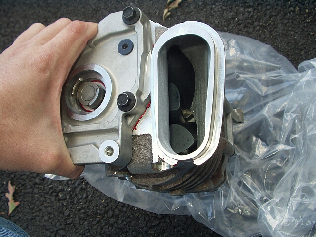
Ok, i think a few of you are confused as to the shape of the stock tube. I hope this clears things up a little.


I was getting the feeling after going through some of these posts that people felt that the tube was continusly reducing in size, it isn't. Any velocity gained by the funneled shape is lost due to the megaphone shape afterwards.
I was getting the feeling after going through some of these posts that people felt that the tube was continusly reducing in size, it isn't. Any velocity gained by the funneled shape is lost due to the megaphone shape afterwards.
#41
11-07-2005 | 02:11 PM
Supercharger intake tube
. �Make the tube, and measure the results.� I agree 100%
Then we can discuss what a meaningful measurement is and how to affect it.
The benefit here as I see it will be less supercharger pumping load when the bypass valve is closed i.e. supercharge mode.
With less parasitic load required to drive the supercharger more usable horse power at the crank. By the way a supercharger (pump) creates both negative and positive pressure i.e. inlet and outlet sides both contribute to the load and the work to drive it.
A Positive Displacement Pump will produce the same flow at a given RPM no matter what the discharge pressure is. This type of pump creates a pulsating or oscillating flow profile at the pump outlet. A Positive Displacement Pump cannot be operated against a closed system on the discharge side of the pump, If a Positive Displacement Pump is allowed to operate against a closed discharge it will continue to produce flow which will increase the pressure in the discharge manifold (intercooler and intake manifold) until either the intercooler or intake manifold bursts or the pump is severely damaged or both.
Not to worry here though because thanks to Mr. Camshaft we can pressurize those cylinders in our partially closed system. But here I digress from the topic at hand.
Last edited by norm03s; 11-07-2005 at 02:21 PM. Reason: add text
#42
11-07-2005 | 02:45 PM

2nd Gear
Joined: Aug 2004
Posts: 131
Likes: 0
Originally Posted by inimmini
Agreed, as long as the speed is not attained at the expense of pressure drop. If the above statement were followed to its logical conclusion, a conical SC tube with an large inlet and an outlet the size of a pinpoint would be ideal. Very fast flow, but little flowrate and a huge pressure drop. Unfortunately, unless you add work to the system, the is no way to gain velocity without losing more potential energy than you gain in kinetic.
#43
11-07-2005 | 03:09 PM
6th Gear
Joined: Jan 2005
Posts: 1,719
Likes: 1
From: New Brunswick, NJ
Originally Posted by autoxguy305
I was getting the feeling after going through some of these posts that people felt that the tube was continusly reducing in size, it isn't. Any velocity gained by the funneled shape is lost due to the megaphone shape afterwards.
. I'm not sure about your calculation for SC inlet area, though... I've taken off and held that tube, my original and new ported SC....and I'm pretty sure that the stock SC duct is not 4 sq. in. It is an oval, yes, so area will be difficult to figure. I am personally of the impression that the TB side is larger. I may be wrong- I have not measured it.
#44
11-07-2005 | 03:53 PM
Where'd it go?
Originally Posted by inimmini
In the experiment described below, if the area of a large tube is progressively decreased, velocity will increase but total flow will decrease.
Matt
ps, there actually is a way to do all this stuff. It's called fluid dynamics. Also, for our pressure and flow regimes, it's not as hard as you would think. It gets messier when you do the pulse stuff, and ressonant phenomina, but average flow for tubes (with and without bends) is described by their conductivity, and it's a lot like 1/resistor values in electrical circuits. So for a linear system of parts (meaning one after the other, not all in a straight line), you can know how the system will flow if you know the conductivity of each part, and the pressure drop accross the system. Watch out for step changes in the parts where they meet, as this screws the math all to hell.
#45
11-07-2005 | 06:43 PM
Thread Starter
|
2nd Gear
Joined: Sep 2005
Posts: 80
Likes: 0
Originally Posted by ingsoc
Good, simple diagrams . I'm not sure about your calculation for SC inlet area, though... I've taken off and held that tube, my original and new ported SC....and I'm pretty sure that the stock SC duct is not 4 sq. in. It is an oval, yes, so area will be difficult to figure. I am personally of the impression that the TB side is larger. I may be wrong- I have not measured it.
. I'm not sure about your calculation for SC inlet area, though... I've taken off and held that tube, my original and new ported SC....and I'm pretty sure that the stock SC duct is not 4 sq. in. It is an oval, yes, so area will be difficult to figure. I am personally of the impression that the TB side is larger. I may be wrong- I have not measured it.
#46
11-07-2005 | 07:04 PM
Where'd it go? Whatever doesn't flow thru the tube stays in the atmosphere! No nuclear reactions needed!
Imagine this: the suction side of a fan is connected to a straight piece of pipe. Let's say there is a pressure tap at the inlet to the fan. When the fan is turned on, the pressure reads slightly less than atmospheric, due to pressure drop at the pipe entrance and along the length of the pipe. This lower pressure makes the fan blow less air than if the pipe were not there, since the vanes have fewer molecules to push against.
Now imagine a "velocity stack" is placed just upstream of the pressure tap. This funnels the flow down, and speeds it up. What do you think happens to the pressure? It goes down further! The fan therefore becomes less efficient, and pumps less air. Has mass been conserved? Sure. Less mass entering, less out. But the velocity stack does not increase mass flow, no way no how.
Of course, in this analogy the pipe is the SC tube, and the fan is the SC.
Originally Posted by Dr Obnxs
Um, can't really, there's conservation of mass to think about (unless this is a Nuclear Intake, or Atomic Gain System!). Mass flux is conserved. Otherwise you'd have a pile of unused gas molecules lying around somewhere....
Matt
ps, there actually is a way to do all this stuff. It's called fluid dynamics. Also, for our pressure and flow regimes, it's not as hard as you would think. It gets messier when you do the pulse stuff, and ressonant phenomina, but average flow for tubes (with and without bends) is described by their conductivity, and it's a lot like 1/resistor values in electrical circuits. So for a linear system of parts (meaning one after the other, not all in a straight line), you can know how the system will flow if you know the conductivity of each part, and the pressure drop accross the system. Watch out for step changes in the parts where they meet, as this screws the math all to hell.
#47
11-08-2005 | 12:54 PM

6th Gear
Joined: Oct 2002
Posts: 3,652
Likes: 4
From: Lansdale, PA
Here's something to think about, with respect to the SID pipe. Unlike in an intake manifold where the air is either flowing into the combustion chamber, or slamming up against the closed intake valve, in the SID, the air is going into the supercharger inlet, which is always open:
The rotors are spinning so the air always has somewhere to go (ie, there is no closed valve for it to hit). Now, it could deflect off the end of rotors but I suspect the inlet air is coming into the supercharger more smoothly and with less pulsing than you'd see in a N/A intake manifold.
The rotors are spinning so the air always has somewhere to go (ie, there is no closed valve for it to hit). Now, it could deflect off the end of rotors but I suspect the inlet air is coming into the supercharger more smoothly and with less pulsing than you'd see in a N/A intake manifold.

Thread
Thread Starter
Forum
Replies
Last Post