When you click on links to various merchants on this site and make a purchase, this can result in this site earning a commission. Affiliate programs and affiliations include, but are not limited to, the eBay Partner Network.
ElectricalFor discussions regarding wiring up electrical modifications such as radar detectors, brake light mods, power sockets, and driving lights in Clubman (R55), Cooper and Cooper S (R56), and Cabrio (R57) MINIs.
Headlights not Bright Enough? Measure their Voltage.
My stock 2014 R56 Mini Hatchback is as basic as you can get. I love it to death, except for the lighting at night. It's like I am driving my 1967 MGA with Lucas Electrics. Totally inadequate illumination.
I investigated (on this forum) about upgrading the stock headlamps (H13) to a brighter version and ran across posts referring the Daniel Stern's lighting web site. In it, he discusses how much illumination you loose with less than full voltage being applied to the headlight bulbs. I measured mine with the car running and lights on by sticking my voltmeter probe into the back of the headlamp connector and then back to the battery terminals. I could see about 14.3 volts available at the battery, I only had 11.2 volts at the bulb inputs. The ground side had very little voltage drop (o.1volts). This loss of 3 volts, according to Daniel's article, caused a 50% loss in illumination. Instead of trying to get a brighter bulb, why not increase the voltage available to the existing bulbs.
The answer is to direct the voltage from the battery through a dedicated relay directly to the headlamps and use heavy gauge wires to minimize loss. Daniel also had a kit that included most of the hard to get parts for making this adaptation. You basically use the existing hi and low beam controls to activate the appropriate dedicated relay to light the hi or lo headlight beams. The only Fly in the Ointment was that the blasted, bulb-out, message will show up on the driver's display and annoy you. This happens even if the headlights are switched off by the control on the turn signal lever. I figured the circuity monitored the current flow to the headlamps and signaled bulb-out whenever it the current dropped below some minimum. I did some experiments and goggled around to find you could put a resistor on the factory power lead to draw enough current to "fool" it into thinking that the lights were not burned out. An H13 bulb draws about 60watts/ 12volts = 5amps, but the detector only needs about 2amps to conclude the lights are ok. 12volts/2amps = 6ohms, but the power being dissipated is 2amps X 12volts = 24 watts, so I chose a 50watt wire wound resistor with a heat sink and mounting tabs. Since only hi or low beams are on, but not both, the current being "lost" is 2amps X 2 bulbs = 4amps. I felt that I could put up with that kind of draw to keep the failure indicators happy. You can cut the total power lost to heat even more if you keep the lights off during the daylight as the failure monitor only has about 5 volts on it to check the lamps. I am also using 12ga. wire for the wires from the B+ 12volt power stud through the relays down to the headlamp bulbs. I am using 14ga. wire for the connections to the 6 ohm resistors and the relay coils.
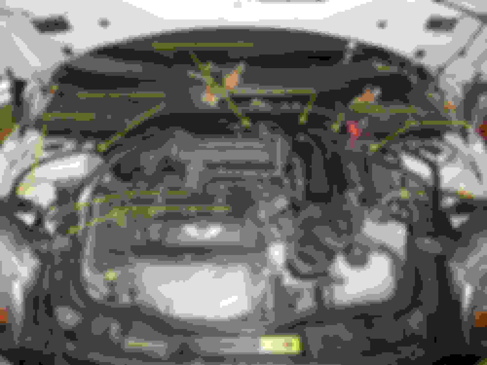
The biggest difficulty is finding any space to under the hood to mount the relay circuit. The following pix shows my circuit diagram and the under hood mounting that I used. Let me say here, I don't know if this will work for your Mini, it worked for mine. But, if your headlights are dim because the voltage at the lights are low, you may be able to make a significant improvement. Before I made the change, my original Mini lost about 3 volts (14.3volts - 11.3volts.= 3volts). With the relay fix, I only am loosing about 0.1volts (14.3volts - 14.2volts = 0.1volts) on the headlamps. This has made a very noticeable difference in the visibility at night. It could be that something was wrong with the Mini headlamp module to loose 3 volts, but this solved it anyway and also prepared me to use more powerful lights if I wanted to. For now, I am satisfied with the stock headlights and my relay fix for acceptable illumination at night.
This is the general schematic for the relay fix. Some parts such as terminal blocks and connectors are not shown on it, but are shown on the next pictorials in this post. Note that the color codes I used for the wiring are completely my own picks based on what I had lying around. I used terminal blocks for many of the three-way splices since I had not been able to find a good choice for a three-way crimp-on connector.

 11-24-2015, 07:27 PM