When you click on links to various merchants on this site and make a purchase, this can result in this site earning a commission. Affiliate programs and affiliations include, but are not limited to, the eBay Partner Network.
The A/C control arrived today. Having the weekend to myself (meaning an utter lack of HoneyDo�s! 🥳 I tore down the module for an autopsy. NOTE: I used a T7 Torx bit to remove the screws. It was a little tight, so if a T6 exists that�s probably what is needed.
This is a very initial post on what I found so far, a few suspicions as to what�s wrong, and two things I found very unusual.
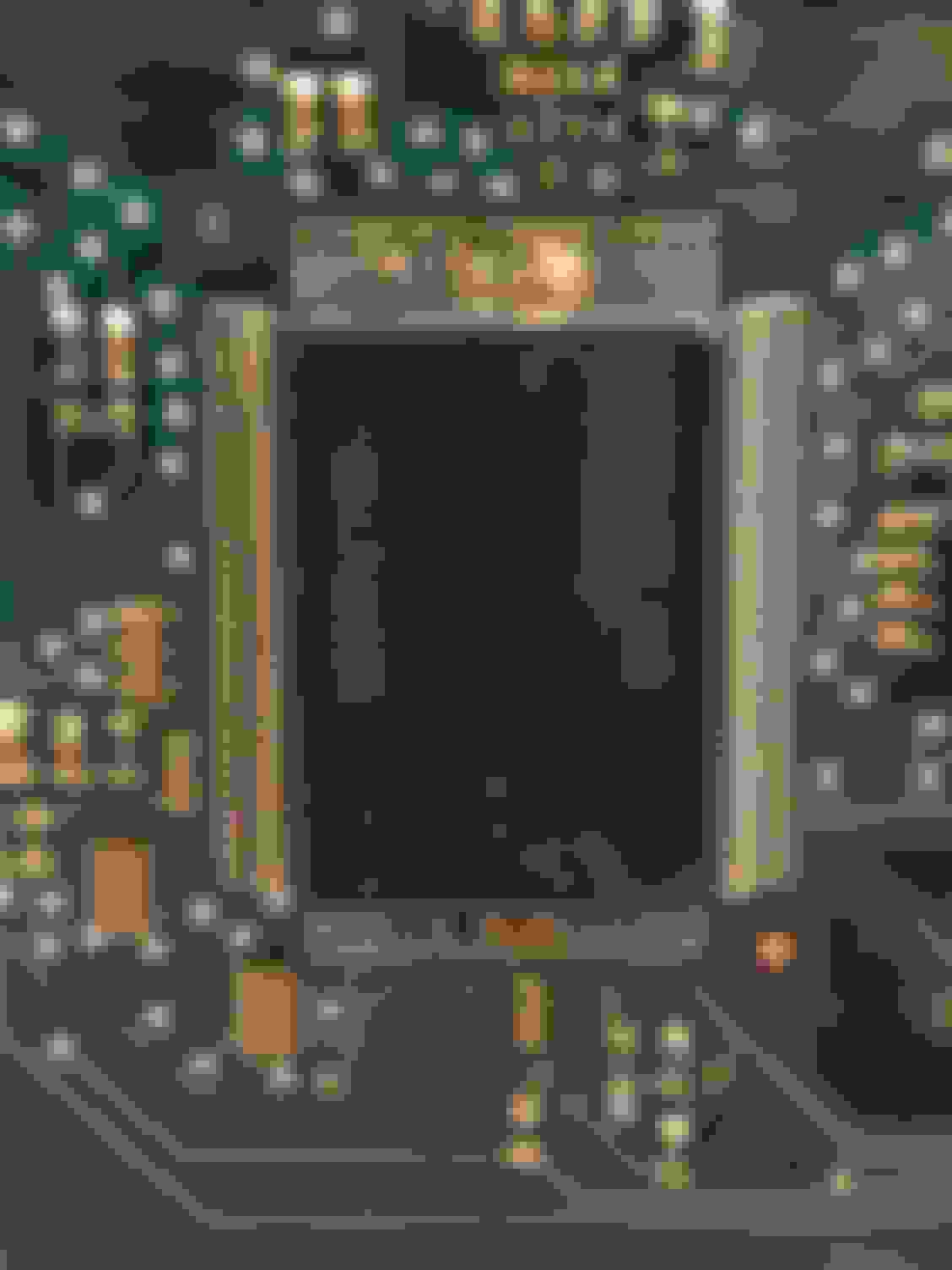
NEC D78F0948GF microcontroller with corrosion on left side of chip Right side of the chip, more corrosion or just plain dirt (?).
Now this is something I�ve never seen before:
This connector looks like it has been shoved into the board, but never soldered!
This is the back side of the connector the wiring harness is plugged into, notice the lack of any solder!
ssoliman is right. Looks like somebody dumped a cola or something in this thing.
This was odd; I�d have expected two lenses or whatever you want to call them for illuminating both the Warm and Cold sides of the ****. There is a clear plastic light guide for the Cool side that�s missing on the Warm side.
What I think is probably a capacitor, before and after:
Before the scrubbing.
After a scrub with a cut down acid brush and some contact cleaner.
More to follow. Any questions so far?
looking at this again, I�m surprised the control panel was working at all. The only thing not working was the temp mixing. Mind blown 🤯
I cleaned up the board today. The crud seems to not have been conductive.
Using the Bentley and those prints that didn�t seem accurate that I posted earlier, I�m tracing back to see what the pins in that header go to on the rest of the HVAC system.
I found the ground that shouldn�t be there, trying to trace it back through the board now.
I�ll do a better write up later, with some more pictures.
Having some trouble back tracking the source of the ground, can�t see under the big white connector on the board. Will probably end up trying to remove it, hopefully it won�t wreck the board. More on that later.
For those who may need to clean sticky buttons, here�s some pics.
To remove a button for cleaning, I used a jewelers screwdriver to release the catch. The best way I found was to go through a small hole on the back side of the board and pry just enough to release the button. Once the button is lifted to the position shown, it can be lifted off. Side view of the button. The small fan is held on with 2 screws, once they�re removed it pulls straight out. I blasted it clean with compressed air, making sure to hold the blades so the air stream wouldn�t spin the blades and damage the bearings. Compressed air can spin a fan or bearing extremely fast.
The center button is held to the faceplate by the four catches, as shown here.
Is there anything else someone would like to see as far as disassembling one of these for cleaning?
Some time I�ll arrange this into a more step-by-step procedure for anyone who needs to work on one of these. To the best of my knowledge they aren�t still in production so the spares that are on the shelves now are all that�s left.
I�m sure they�re still available, but to the best of my knowledge they aren�t in production. (I could be wrong.) So the spares that are on the shelves are all there is.
My intent is to make the spare parts supply last longer, and fix ones that are repairable so they don�t get tossed in the trash. And of course to help somebody keep from spending a couple hundred bucks or whatever they cost for a new one.
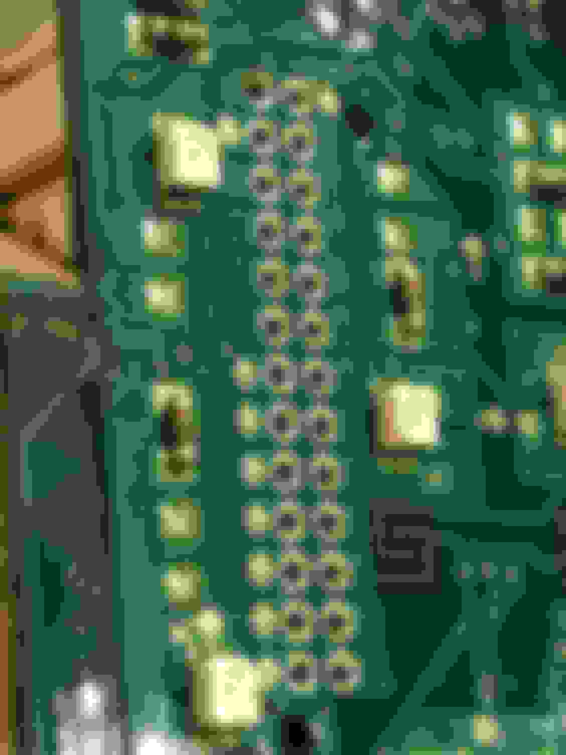
Edit: It looks like the problem is the chip circled in red. TLE6208-3G available at Mouser Electronics.
As of this writing it looks like the chip in the upper right hand corner has failed. One more test before I�m sure.
It is odd how this system works and may have misdiagnosed mine. I replaced the temp door control motor, the door does not react right away. I put it on hi heat and there is a delay then the door works. That was not the heat problem on mine, found there was blockage in the heater core and replaced it now it will cook you on high! I sprug for a Nessin brand and the only issue was could not get the pipes in far enough to install the retainer clamps. I reinstalled the old ones and it fit perfect!

 01-31-2021, 12:47 PM


 I tore down the module for an autopsy. NOTE: I used a T7 Torx bit to remove the screws. It was a little tight, so if a T6 exists that�s probably what is needed.