When you click on links to various merchants on this site and make a purchase, this can result in this site earning a commission. Affiliate programs and affiliations include, but are not limited to, the eBay Partner Network.
Stock Problems/IssuesDiscussions related to warranty related issues and repairs, or other problems with the OEM parts and software for MINI Clubman (R55), Cooper and Cooper S(R56), and Cabrio (R57).
I am questioning the order of wires to the electrical connector on my Camshaft Position Sensor (exhaust). This is the plain jane R56, N12 (07) non turbo.
Can someone verify? At one point I changed the connector plugs on exhaust and intake (the N12 has 2 sensors) and now before I start "Betsy" I want to make sure I have orange and yellow in correct order (position).
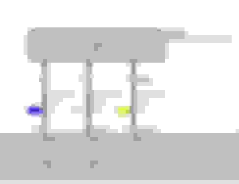
1. When I look up the wiring diagram is shows the three wires as blue, yellow and white. Blue on the left, yellow in the middle and white on the right. What's the build date of your car? Sometimes Mini changes these things mid cycle.
2. The diagram shows the wire colors and positions exactly the same as the intake cam sensor. So compare against that one to see if it matches.
3. In your pic the connector looks a little "off." As if the plug is two pieces and beginning to separate.
mine is an 07 N12, R56 non T. I read an article on Pelican and they indicted the sensor signal was on the right (T3) and supply (12V) was on the left (T1). I had replaced the connectors and I though perhaps I misplaced them. Even though I had photos it made me think this was part of my issue. I am waiting on a new connector for an injector or I would have already started it up.
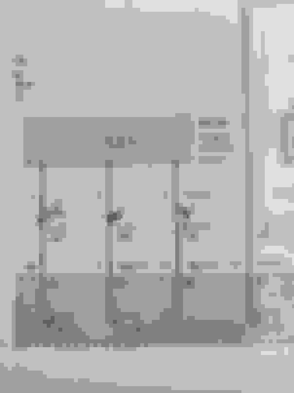
The Bentley shows this pic. I don't read electric symbols. I can't tell if they are in any sort of order, left to right
MrBean, the reason the plug looks a little off is the clip on the outside is not seated. I just haven't closed it it off till I discovered if they were in correct order.
It's not a game ender. I should have the injector connector shortly and I'll do the smoke test, right? I used to hear electricians call powering up their work, using this saying.
Here's the wiring diagram I have, obviously it's not entirely correct but does seem to correlate with yours (at least well enough that we can figure this out).
When looking at your connector, pin 1 is on the left, 2 is in the middle and 3 is on the right. You can confirm this by unplugging the connector and looking at the end of it. There should be a barely legible "1" and "3" molded into the plastic adjacent to pins 1 and 3, respectively.
A word about the diagrams, they show pin 2 on the right and 3 in the middle, this is a formatting error that does not translate to the physical connector. So, according to your wiring diagram, the wires should be orange, yellow, then white when going from left to right on the connector. By your picture above it looks like the wires aren't in there correctly.
When I dig deeper into my diagram, pin 1 is 5V supply, pin 2 is the signal to the DME and pin 3 is ground. So per my previous post, if you back-probe between pins 2 and 3 you should be measuring the signal.
edit: I've worked with many different electrical engineers over the years, and yes, they all call it a smoke test.
Shows pin number
Well, MrBean you called it correctly. The pin numbers were inside the sensor. Now I question the sequence order again. Does the Bentley diagram show 1, 2, 3 as if looking into the sensor, from the camera view attached? It means white (ground) is on left. My head hurts. I get the connector for fuel injector tomorrow. I may move those pins around on the cam sensor.
My issue is the DME. The sensor is operating properly. The supply shows battery voltage, move the cam to TDC and it shows zero volts. Yep the Hall effect.
I learned a great deal about the Bentley manual as well. The pin detail in the electrical portion is spot on. I"m impressed.
Thanks again MrBean
Schematics for electronics are not supposed to be drawn to match the physical part. They are drawn for ease of reading. In this case, note that pins 1 and 3 both route to X60211, while pin 2 routes to X60212. It's just easier for the draftsman to draw and the technician to read. Imagine trying to draw these two X60211 wires following your "match the connector" concept.
Schematics for electronics are not supposed to be drawn to match the physical part. They are drawn for ease of reading. In this case, note that pins 1 and 3 both route to X60211, while pin 2 routes to X60212. It's just easier for the draftsman to draw and the technician to read. Imagine trying to draw these two X60211 wires following your "match the connector" concept.
I am trying to check the connections to the camshaft sensors on my 2011 justa. Please see the thread here
can someone tell the PIN numbers shown in the above diagram (38, 7, 15) on the ECU side correspomd to which connector: I see three connectors on the ECU, one small and two large.

 08-31-2021 | 07:53 PM